Blood vessel anastomat for kidney transplantation operation

A technology for surgery and kidney transplantation, which is applied in the field of vascular staplers for kidney transplantation surgery, which can solve the problems of long anastomosis time, long operation time, and the operation quality is easily affected by doctors' psychological and physiological fluctuations, so as to reduce pain and facilitate operation. The effect of vascular anastomosis

Active Publication Date: 2021-10-29
PEOPLES HOSPITAL OF HENAN PROV
View PDF16 Cites 0 Cited by
  • Summary
  • Abstract
  • Description
  • Claims
  • Application Information

AI Technical Summary

Problems solved by technology

Although the suture anastomosis technique is currently recognized as the standard method of vascular anastomosis, there are still some problems: cumbersome operation, long operation time, high requirements for doctors' skills, and it is difficult to master the essentials of operation in a short time without training. At the same time, the quality of surgery is easily affected by the psychological and physiological fluctuations of doctors.
At present,...

Method used


Image

  • Blood vessel anastomat for kidney transplantation operation
  • Blood vessel anastomat for kidney transplantation operation
  • Blood vessel anastomat for kidney transplantation operation

Examples


Embodiment 1

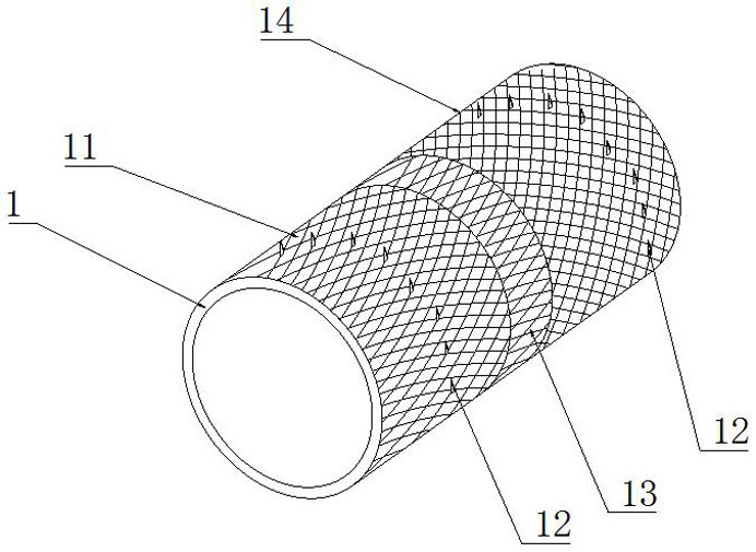
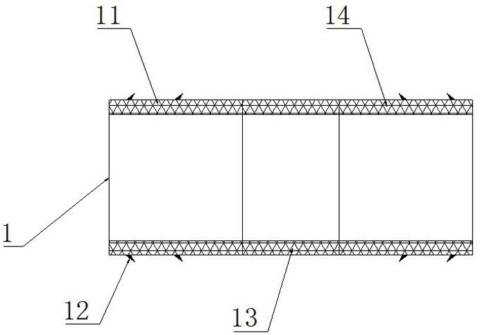
[0023] Such as Figure 1-3 A blood vessel stapler for kidney transplantation shown, a blood vessel stapler for kidney transplantation, includes an inner tube main body 1, the inner tube main body 1 includes a left inner tube 11, and the left inner tube 11 is provided with a Fixed teeth 12, the left inner tube 11 is provided with a middle tube 13 fixedly connected with it, the middle tube 13 is provided with a right inner tube 14 fixedly connected with it, and the right inner tube 14 is provided with a fixed tooth 12 fixedly connected with it, The left inner tube 11 , the middle tube 13 and the right inner tube 14 are provided with hollow grids; the outer surface of the inner tube main body 1 is provided with a reinforcement layer 15 , and the inner surface of the main pipe main body 1 is provided with an anticoagulation layer 16 .

[0024] The intima of the left and right blood vessels are everted and then the intima is wrapped on the fixed teeth 12 on the left inner tube 11 a...

Embodiment 2

[0026] Such as Figure 4-8 The main body of the inner tube 1 is provided with a vascular scissors 2, the vascular scissors 2 includes a left scissors 21 and a right scissors 22, the left scissors 21 is provided with a ring ring at one end, and the left scissors 21 is provided with a shearing part 23 at one end.

[0027] The shearing part 23 comprises a ring shear 231, the first shearing part 232 is provided on the inner wall of the ring shear 231, the ring shear 231 is provided with a shear seam 234, and the shear seam 234 is provided with the right shear 22 and is fixedly connected with the shear. The second cutting part 235 matched with the slit 234 is provided with a collecting box 233 on the ring cutting part 231 .

[0028] The inner tube main body 1 is provided with an outer tube 3 matched with it. The outer tube 3 includes a left outer tube 31 and a right outer tube 33. The left outer tube 31 is provided with a fixing ring 32 fixedly connected with it. Fixing nails 34 a...


PUM


Abstract

The invention belongs to the technical field of medical instruments, and discloses a blood vessel anastomat for a kidney transplantation operation. An inner tube main body comprises a left inner tube; fixed teeth fixedly connected with the left inner tube are arranged on the left inner tube; a middle tube fixedly connected with the left inner tube is arranged on the left inner tube; a right inner tube fixedly connected with the middle tube is arranged on the middle tube; fixing teeth fixedly connected with the right inner tube are arranged on the right inner tube; and hollow grids are arranged on the left inner tube, the middle tube and the right inner tube. According to the blood vessel anastomat, through the inner tube main body made of a shape memory material, the left inner tube and the right inner tube are expanded at phase-change temperature, and the middle tube is shrunk at the phase-change temperature, to make blood vessels on the two sides attached.

Description

technical field [0001] The invention belongs to the technical field of medical instruments, and in particular relates to a blood vessel stapler for kidney transplantation. Background technique [0002] The technique of vascular anastomosis is the basis of microsurgery and the whole surgery. The ideal vascular anastomosis method should be easy to master, easy to operate, short anastomosis time, and less harmful to blood vessels. Currently, vascular anastomosis techniques mainly include suture anastomosis technique, vascular mechanical anastomosis technique, and vascular bonding technique. Suture anastomosis techniques and mechanical anastomosis techniques are commonly used in clinical practice at present. Although the suture anastomosis technique is currently recognized as the standard method of vascular anastomosis, there are still some problems: cumbersome operation, long operation time, high requirements for doctors' skills, and it is difficult to master the essentials of...

Claims


Application Information

Patent Timeline
IPC IPC(8): A61B17/11A61F2/06
CPCA61B17/11A61F2/064A61B2017/1107A61F2210/0004A61F2210/0014
Inventor 王俊鹏李鑫闫天中武小强曹广辉王志为杨中南
Owner PEOPLES HOSPITAL OF HENAN PROV
Why Eureka
Try Eureka