Jet-propelled shell-and-tube heat exchanger

A shell-and-tube heat exchanger, jet technology, applied in indirect heat exchangers, heat exchanger types, heat exchanger shells, etc., can solve the problem of less research on gas heat exchangers, uneven fluid distribution, and internal baffles. The design involves less problems, and achieves the effect of strengthening heat exchange and descaling, uniform heat exchange, and enlarging the area.

Inactive Publication Date: 2021-10-26
SHANDONG UNIV
View PDF0 Cites 0 Cited by
  • Summary
  • Abstract
  • Description
  • Claims
  • Application Information

AI Technical Summary

Problems solved by technology

[0008] In addition, the current shell-and-tube heat exchangers have little research on gas heat exchangers, and the design of internal baffles is less involved, resulting in the problem of uneven fluid distribution

Method used


Image

  • Jet-propelled shell-and-tube heat exchanger
  • Jet-propelled shell-and-tube heat exchanger
  • Jet-propelled shell-and-tube heat exchanger

Examples


Embodiment Construction

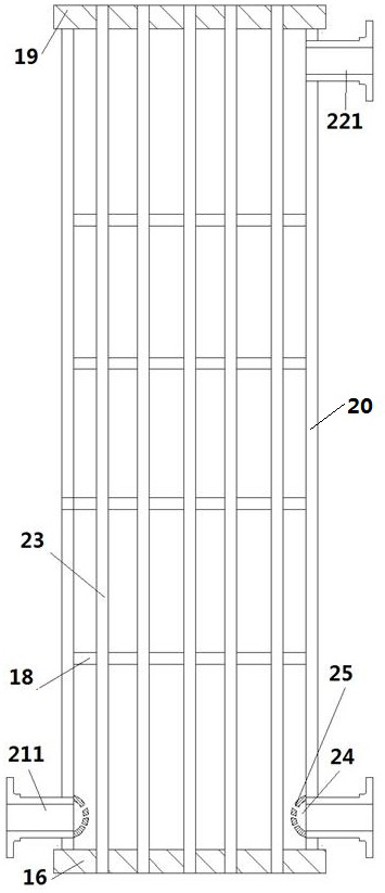
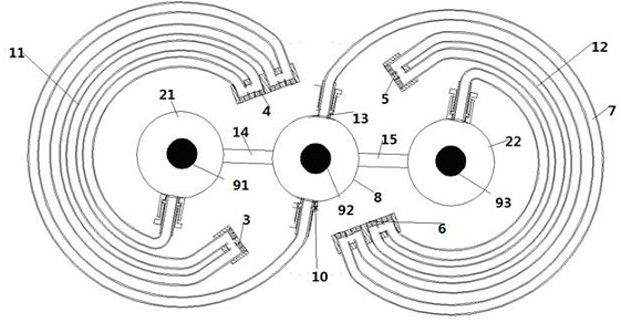
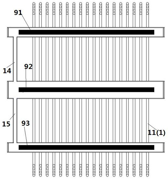
[0035] A jet-type shell-and-tube heat exchanger, such as figure 1As shown, the shell-and-tube heat exchanger includes a shell 20, a heat exchange component 23, a shell-side inlet connection 211 and a shell-side outlet connection 221; the shell-side inlet connection 211 and the shell-side outlet connection 221 are respectively located in the The lower end and the upper end of the heat exchanger; the heat exchange component 23 is arranged in the shell 20, and the heat exchange component is fixedly connected to the upper tube plate 16 and the lower tube plate 19; the shell side inlet connection 211 and the shell side outlet connection 221 are all arranged on the shell 20; the gas enters from the shell-side inlet connecting pipe 211, passes through the heat exchange components for heat exchange, and exits through the shell-side outlet connecting pipe 221.

[0036] Preferably, the heat exchange component extends along the vertical direction. The heat exchangers are arranged vertic...


PUM


Abstract

The invention provides a jet-propelled shell-and-tube heat exchanger. The jet-propelled shell-and-tube heat exchanger is characterized in that the end part of each shell pass inlet connecting pipe is of a spray head structure, a plurality of horizontal baffles are arranged in a shell, the baffles extend the whole cross section of the shell, and holes for heat exchange components to penetrate through are formed in the baffles; gas holes are formed in the baffles; spray pipes are arranged on the wall surface of the shell, and spray holes are formed in the spray pipes; and the spray pipes are arranged around the vertical inner wall of the shell for a whole circle. The baffles and the spray pipes are arranged around the vertical inner wall of the shell for a whole circle, so that the heat exchange time is prolonged, surrounding fluids are uniformly distributed, and heat can be fully and uninterruptedly utilized.

Description

technical field [0001] The invention relates to a shell-and-tube heat exchanger, in particular to an air jet shell-and-tube heat exchanger. Background technique [0002] Shell-and-tube heat exchangers are widely used in chemical, petroleum, refrigeration, nuclear energy and power industries. Due to the worldwide energy crisis, in order to reduce energy consumption, the demand for heat exchangers in industrial production is also increasing. The quality requirements for heat exchangers are also getting higher and higher. In recent decades, although compact heat exchangers (plate, plate-fin, press-welded plate heat exchangers, etc.), heat pipe heat exchangers, direct contact heat exchangers, etc. have been developed rapidly, but due to the The heat exchanger has a high degree of reliability and wide adaptability, and it still occupies a dominant position in output and consumption. According to relevant statistics, the current consumption of shell-and-tube heat exchangers in in...

Claims


Application Information

Patent Timeline
Patent Type & Authority Applications(China)
IPC IPC(8): F28D7/16F28F9/22F28F9/24F28F13/12F28F27/00
CPCF28D7/1676F28F9/22F28F9/24F28F13/12F28F27/00Y02P20/10
Inventor 冷学礼余显晟王进张冠敏修蓬岳邱燕其他发明人请求不公开姓名
Owner SHANDONG UNIV
Why Eureka
Try Eureka