FFC flat cable tension testing machine
A technology for tensile testing and flat cables, which is applied in the direction of applying stable tension/pressure to test material strength, measuring devices, instruments, etc., and can solve the problems of low efficiency, time-consuming and labor-intensive testing of tension
- Summary
- Abstract
- Description
- Claims
- Application Information
AI Technical Summary
Problems solved by technology
Method used
Image
Examples
Embodiment 1
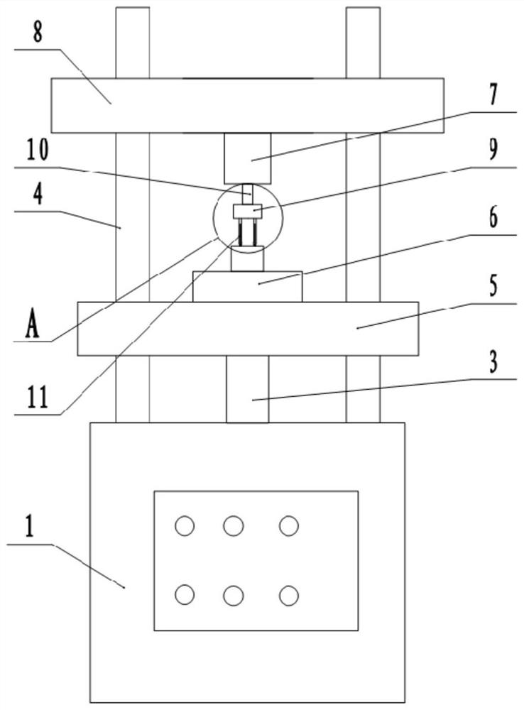
[0027] The embodiment is basically as attached figure 1 Shown: FFC flat cable tensile testing machine, including the operation box 1, the top of the operation box 1 is fixedly connected with two guide rods 4 arranged symmetrically, the guide rod 4 is provided with a horizontal plate 8 and a support plate 5, the horizontal plate 8 is located on Above the support plate 5, there is a fixture 6 on the support plate 5. The fixture 6 in this embodiment is fixedly connected to the support plate 5 through bolts. The fixture 6 is used to clamp and fix the FFC flat cable. There is a fixture on the full-automatic insertion force testing machine in the art.
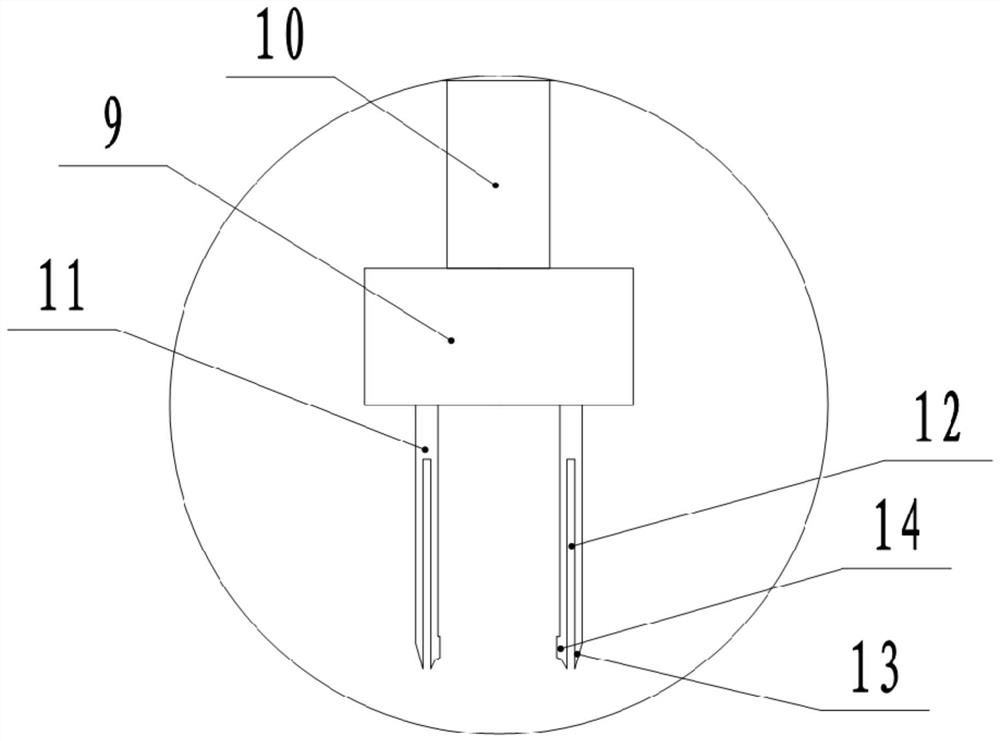
[0028] In this embodiment, the horizontal plate 8 is fixedly connected with the guide rod 4, the support plate 5 is vertically slidably matched with the guide rod 4, the two guide rods 4 pass through the support plate 5, and the operation box 1 is provided with a drive support plate 5 vertically Sliding drive unit, the drive unit in...
Embodiment 2
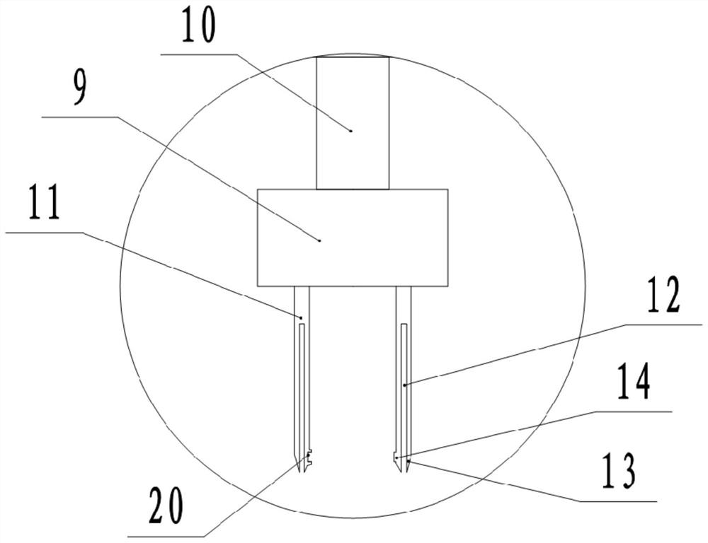
[0038] Such as image 3As shown, the difference between the FFC flat cable tensile testing machine and the first embodiment is that a groove 20 is provided on the end surface of one of the two clamping parts 14, and a convex groove is provided on the other clamping part 14. The protrusion can be inserted into the groove 20.
[0039] In this solution, when the two jaws 11 are closed together, the groove 20 of one of the clamping parts 14 can be made to cooperate with the protrusion of the other clamping part 14, even if the protrusion of one of the clamping parts 14 The part is inserted into the groove 20 of another clamping part 14, so that the metal wire can be clamped tighter, the clamping force generated on the metal wire is better, and it is more stable in the process of the tensile test, and the metal wire is not easy to be separated from the two sides. The jaws 11 fall off.
Embodiment 3
[0041] Such as Figure 4 As shown, the difference between the FFC flat cable tensile testing machine and the first embodiment is that the jig 6 is provided with a horizontally arranged slot 19, the right end of the slot 19 communicates with the right end of the jig 6, and the top of the slot 19 is At the open end, the front and rear sides of the slot 19 are provided with a splint 18 and a power piece that drives the splint 18 to slide in a direction perpendicular to the slot 19 .
[0042] The power parts in this embodiment are all clamping cylinders 15, and both sides of the slot 19 are provided with sliding chambers 16. One side is provided with a mounting cavity 17, two clamping cylinders 15 are respectively located in the mounting cavity 17, the sliding cavity 16 is connected with the slot 19 and the mounting cavity 17, and the output shaft of the clamping cylinder 15 passes through the two splints 18 respectively. Screw secure connection.
[0043] This embodiment provide...
PUM
 Abstract
Description
Claims
Application Information
 - R&D
- Intellectual Property
- Life Sciences
- Materials
- Tech Scout
- Unparalleled Data Quality
- Higher Quality Content
- 60% Fewer Hallucinations
Browse by: Latest US Patents, China's latest patents, Technical Efficacy Thesaurus, Application Domain, Technology Topic, Popular Technical Reports.
© 2025 PatSnap. All rights reserved.Legal|Privacy policy|Modern Slavery Act Transparency Statement|Sitemap|About US| Contact US: help@patsnap.com


