
Heat pipe flue gas heat exchanger

A flue gas heat exchanger and heat pipe technology, which is applied in the direction of heat exchanger shell, indirect heat exchanger, heat exchange equipment, etc., can solve the problems of high manufacturing cost of heat pipe, increased fan energy consumption, and aggravated local wear, etc., to achieve equipment The overall life is long, the operation cost is reduced, and the effect of avoiding low temperature corrosion

Active Publication Date: 2021-10-22
FUJIAN LONGKING
View PDF6 Cites 0 Cited by
  • Summary
  • Abstract
  • Description
  • Claims
  • Application Information

AI Technical Summary

Problems solved by technology

When the waste heat recovery flue gas temperature is high, high-temperature heat pipe working fluid is required, and the heat pipe manufacturing cost is high; and the temperature inside the pipe is high, and the pressure of the working medium inside the heat pipe is high, so a large pipe wall thickness is required, which further increases the heat pipe manufacturing cost
In addition, there are also operational safety issues with high-temperature heat pipes
[0006] Although the method of using corrosion-resistant stainless steel can improve the service life of the heat exchanger, it directly leads to a double increase in the manufacturing cost of the heat exchanger, which is not conducive to the popularization and application of the product
[0007] In addition, in order to prevent the formation of flue gas corridors and aggravate local wear and tear of the flue gas heat exchanger, the distance between the bottom plate of the heat exchanger and the heat exchange tubes is very small. When the heat exchanger operates for a long time and at low wind speed, dust in the flue gas The problem of sediment accumulation on the bottom plate of heat exchanger
Dust accumulation in the heat exchanger will lead to increased wind resistance, insufficient fan output or a sharp increase in fan energy consumption, which is not conducive to the economical operation of the equipment
Soot blowing equipment is generally used for the prevention of dust accumulation in existing heat exchangers, which can only remove the dust accumulation within the coverage area of ​​the equipment, and has limited effect on the removal of dust at the bottom of the heat exchanger and larger particle sizes, especially when the equipment is running at low load , the flue gas flow rate is significantly lower than the reasonable design value, and the dust cannot be taken away from the heat exchanger in time. Most of the dust settles and stays on the bottom plate of the heat exchanger, which aggravates the dust accumulation and blockage of the heat exchanger
The gap between the bottom plate of the heat exchanger and the heat exchange tubes is very small, even during the maintenance shutdown period, the dust that settles or accumulates on the bottom plate of the heat exchanger cannot be removed manually

Method used


Image

  • Heat pipe flue gas heat exchanger
  • Heat pipe flue gas heat exchanger

Examples


Embodiment Construction

[0032] In order to make those skilled in the art better understand the technical solutions of the present invention, the present invention will be further described in detail below with reference to the accompanying drawings and specific embodiments.

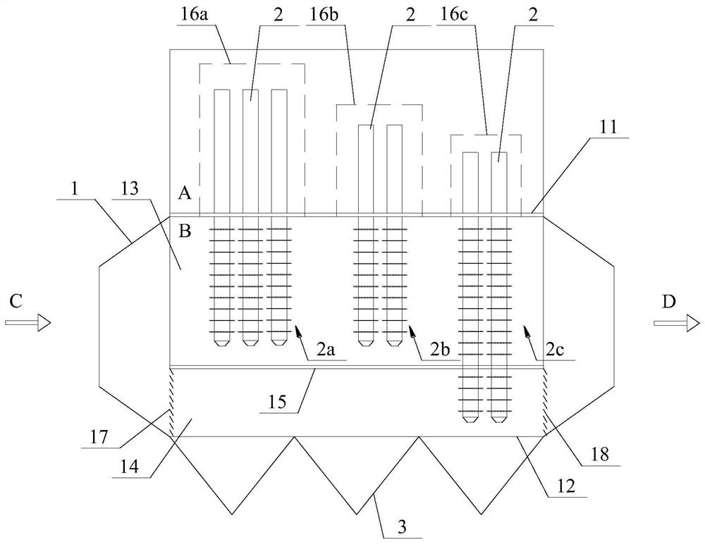
[0033] Without loss of generality, this implementation is based on figure 1 The heat pipe flue gas heat exchanger shown in is the main body of description, and the structural optimization scheme for the heat pipe heat exchanger is explained in detail. It should be understood that, as a typical heat pipe heat exchanger, the specific implementation of the fixed heat pipe inserted in the shell and the ash hopper set at the bottom of the shell is not the core invention of the application, and does not constitute a claim for protection of the application. The heat exchanger constitutes a substantial limitation.

[0034] Please refer to 1, which shows a schematic diagram of the overall structure of the heat pipe flue gas heat exchang...


PUM


Abstract

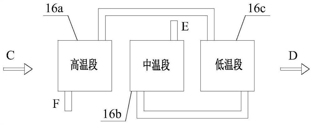
The invention discloses a heat pipe flue gas heat exchanger. The heat pipe flue gas heat exchanger comprises a shell and a plurality of heat pipes inserted into the shell, wherein an inner cavity of the shell is vertically divided into a cold source cavity and a smoke cavity, the smoke cavity is provided with a smoke inlet and a smoke outlet which are used for communicating with a flue, an ash hopper is arranged below a shell bottom plate located at the bottom of the smoke cavity, the smoke cavity is vertically divided into a main flow area and a flow guide area, the heat pipes are arranged in groups, the high-temperature section heat pipe groups are located on the side, close to the smoke inlet, in the shell, the bottom ends of the evaporation sections of the high-temperature section heat pipe groups are located in the main flow area, the low-temperature section heat pipe groups are located on the side, close to the smoke outlet, in the shell, and the bottom ends of the evaporation sections of the low-temperature section heat pipe groups are located in the flow guide area. Through solution optimization, the phenomenon that smoke corrodes the heat pipes is avoided, meanwhile dust accumulation on the bottom plate of the heat exchanger can be effectively avoided, compared with the prior art, according to the solution, the problems that the temperature of the pipe walls of the heat pipes is low and dust is accumulated are fundamentally solved from the heat exchange principle of the heat pipe heat exchanger and the dust accumulation generation mechanism.

Description

technical field [0001] The invention relates to the technical field of waste heat recovery of flue gas, in particular to a heat pipe flue gas heat exchanger. Background technique [0002] As a high-efficiency heat exchange element, heat pipes are widely used in chemical, metallurgical and other industries. The heat pipe heat exchanger is mainly used for waste heat recovery of flue gas, and the recovered heat is used to heat water or materials, and can also be used to heat flue gas, such as coolers and reheaters in MGGH. Based on the lower temperature of the heated cold source, the temperature of the tube wall of the heat pipe heat exchange element is relatively low, and placing it in the flue gas containing acid gas will cause the acid gas to condense below the dew point temperature, and the condensed acid will adhere to the tube wall. When the system runs for a long time, the pipe wall is corroded or even corroded and perforated, which endangers the safety and stability of...

Claims


Application Information

Patent Timeline
Patent Type & Authority Applications(China)
IPC IPC(8): F28D15/02F28F9/22F23J15/02
CPCF28D15/025F28F9/22F23J15/022Y02E20/30
Inventor 谢庆亮谢山样章华熔黄举福廖增安游若晖
Owner FUJIAN LONGKING
Learn More