
Anti-residue reaming forming device suitable for flange machining

A forming device and flange technology, applied in metal processing equipment, metal processing machinery parts, manufacturing tools, etc., can solve the problems of unfavorable iron scrap collection, affecting the use efficiency of drill bits, affecting the positioning of laser pointers, etc., and achieve the effect of cost saving

Inactive Publication Date: 2021-10-22
陈刚
View PDF19 Cites 1 Cited by
  • Summary
  • Abstract
  • Description
  • Claims
  • Application Information

AI Technical Summary

Problems solved by technology

[0002] After the company produces the flange, in order to meet the customer's aperture requirements, it is necessary to use a reaming device to ream the flange at this time. Patent No. CN201921434030.8 proposes "a reaming and forming device for processing flanges" , which absorbs the heat generated by the friction between the drill bit and the flange through the nozzle, and at the same time can absorb the iron filings generated by the drill bit reaming, so that the waste water in the protective tank is discharged through the drain pipe, and the iron filings remain at the bottom of the protective tank. The filter screen is reused after being filtered. Although it solves the problem that the splashed iron filings will damage the staff when the flange is reaming, which is not conducive to the collection of iron filings, and the problem that a large amount of heat is generated during the reaming of the drill bit will affect the efficiency of the drill bit. In actual use, the bottom of the protective tank is horizontal, resulting in a small amount of iron filings remaining far away from the filter, which makes it inconvenient to collect the iron filings in the protective tank, and it passes through the laser pointer The emitted light passes through the mounting hole of the flange, which can further locate the mounting hole of the flange that needs to be reamed. However, since the laser pointer is located under the drill bit, it is easy for the iron filings falling with the water to cover the laser pointer and affect the laser pointer. Position the mounting holes of the next group of flanges. For this purpose, we propose an anti-residue reaming forming device suitable for flange processing

Method used


Image

  • Anti-residue reaming forming device suitable for flange machining
  • Anti-residue reaming forming device suitable for flange machining
  • Anti-residue reaming forming device suitable for flange machining

Examples


Embodiment 1

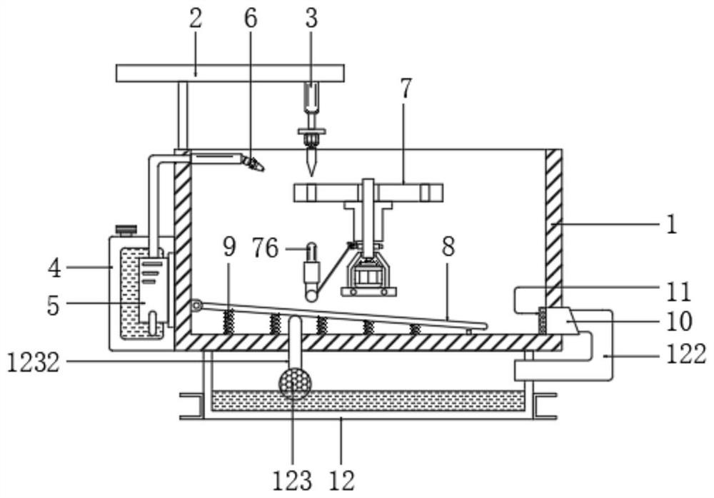
[0022] Anti-residue reaming forming unit for flange machining, see figure 1 and Figure 6 , comprising a protective groove 1, the top left side of the protective groove 1 is provided with a mounting frame 2, the bottom of the mounting frame 2 is connected with a reamer 3, the reamer 3 is the same as the prior art, and it includes a mounting frame 2 Electric push rod, the power end of the electric push rod is connected to the drive motor, and the power end of the drive motor is connected to the drill bit. The left bottom of the protective tank 1 is provided with a clean water tank 4 and a water pump 5 in sequence from back to front. The water inlet of the water pump 5 is connected to the clean water The tank 4 is connected, the water outlet of the water pump 5 is connected with the nozzle 6, the nozzle 6 is located on the top of the inner wall on the left side of the protective tank 1, the inner wall of the protective tank 1 is provided with an auxiliary mechanism 7, and the bo...

Embodiment 2

[0025] Anti-residue reaming forming unit for flange machining, see figure 1 and figure 2 , including a protective tank 1, the top left side of the protective tank 1 is provided with a mounting frame 2, the bottom of the mounting frame 2 is connected with the reamer 3, and the left bottom of the protective tank 1 is sequentially provided with a clean water tank 4 and a water pump from back to front 5. The water inlet of the water pump 5 is connected to the clean water tank 4, and the water outlet of the water pump 5 is connected to the nozzle 6. The nozzle 6 is located on the top of the inner wall on the left side of the protective tank 1. The inner wall of the protective tank 1 is provided with an auxiliary mechanism 7. The protective tank 1 The bottom of the inner wall on the left side is hinged with a slant plate 8, and the bottom of the slant plate 8 is uniformly provided with a spring 9, and the bottom of the spring 9 is connected to the bottom inner wall of the protectio...

Embodiment 3

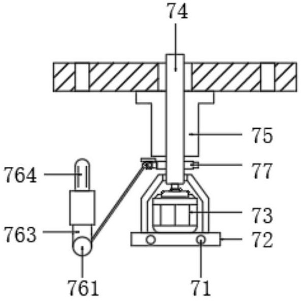
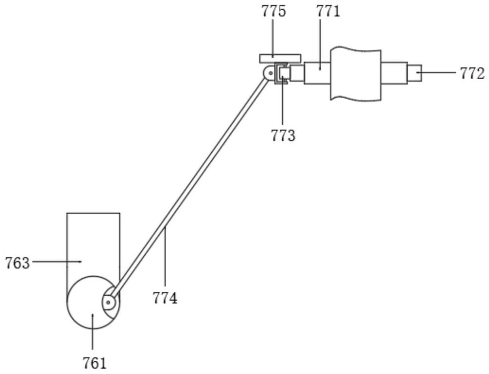
[0029] Anti-residue reaming forming unit for flange machining, see Figure 1 to Figure 5, including a protective tank 1, the top left side of the protective tank 1 is provided with a mounting frame 2, the bottom of the mounting frame 2 is connected with the reamer 3, and the left bottom of the protective tank 1 is sequentially provided with a clean water tank 4 and a water pump from back to front 5. The water inlet of the water pump 5 is connected to the clean water tank 4, and the water outlet of the water pump 5 is connected to the nozzle 6. The nozzle 6 is located on the top of the inner wall on the left side of the protective tank 1. The inner wall of the protective tank 1 is provided with an auxiliary mechanism 7. The protective tank 1 The bottom of the inner wall on the left side is hinged with a slant plate 8, and the bottom of the slant plate 8 is uniformly provided with a spring 9, and the bottom of the spring 9 is connected to the bottom inner wall of the protection g...


PUM


Abstract

The invention discloses an anti-residue reaming forming device suitable for flange machining. The anti-residue reaming forming device comprises a protection groove, a mounting frame is arranged on the left side of the top of the protection groove, the bottom of the mounting frame is connected with a reamer, and a clear water tank and a water pump are sequentially arranged at the bottom of the left side of the protection groove from back to front; and a water inlet of the water pump communicates with the clear water tank, a water outlet of the water pump communicates with a spray head, the spray head is located at the top of the inner wall of the left side of the protection groove, an auxiliary mechanism is arranged on the inner wall of the protection groove, and an inclined plate is hinged to the bottom of the inner wall of the left side of the protection groove. When a roller moves horizontally, a pressing rod drives a sliding rod to move vertically so as to enable a second spring stretch out and draw back to drive a connecting rod to drive a laser pen to move back and forth, scrap iron covering the laser pen can be shaken off, and the scrap iron is prevented from influencing positioning of a flange mounting hole by the laser pen.

Description

technical field [0001] The invention relates to the technical field of flange processing, in particular to an anti-residue reaming forming device suitable for flange processing. Background technique [0002] After the company produces the flange, in order to meet the customer's aperture requirements, it is necessary to use a reaming device to ream the flange at this time. Patent No. CN201921434030.8 proposes "a reaming and forming device for processing flanges" , which absorbs the heat generated by the friction between the drill bit and the flange through the nozzle, and at the same time can absorb the iron filings generated by the drill bit reaming, so that the waste water in the protective tank is discharged through the drain pipe, and the iron filings remain at the bottom of the protective tank. The filter screen is reused after being filtered. Although it solves the problem that the splashed iron filings will damage the staff when the flange is reaming, which is not cond...

Claims


Application Information

Patent Timeline
Patent Type & Authority Applications(China)
IPC IPC(8): B23B41/00B23B47/00B23Q11/10
CPCB23B41/00B23B47/00B23Q11/10
Inventor 陈刚
Owner 陈刚
Learn More