
Anti-corrosion treatment equipment for copper wire connection of transformer substation and operation method thereof

A technology for anti-corrosion treatment and substation, which is applied in the direction of surface pretreatment, coating, and devices for applying liquid to the surface. Anti-corrosion effect, improve work efficiency, easy to use effect

Active Publication Date: 2021-10-22
SUWEN ELECTRIC ENERGY TECH
View PDF7 Cites 0 Cited by
  • Summary
  • Abstract
  • Description
  • Claims
  • Application Information

AI Technical Summary

Problems solved by technology

[0002] The substation refers to the place where the voltage and current are transformed, received and distributed in the power system. The substation in the power plant is a step-up substation. Its function is to boost the power generated by the generator and feed it to the high-voltage power grid. Due to the complex environment of the substation, corrosion problems at the copper wires of the substation are often caused by problems such as humidity and harsh environment. In order to ensure the long-term stable operation and safety of the substation, it is necessary to strengthen the anti-corrosion treatment of the copper wires. The existing anti-corrosion treatment The equipment cannot carry out anti-corrosion treatment on the connected copper wire at any time, the flexibility is poor, and the effect of anti-corrosion treatment is not ideal, and the operation steps are complicated and affect the use

Method used


Image

  • Anti-corrosion treatment equipment for copper wire connection of transformer substation and operation method thereof
  • Anti-corrosion treatment equipment for copper wire connection of transformer substation and operation method thereof
  • Anti-corrosion treatment equipment for copper wire connection of transformer substation and operation method thereof

Examples


Embodiment Construction

[0035] In order to make the technical means, creative features, goals and effects achieved by the present invention easy to understand, the present invention will be further described below in conjunction with specific embodiments.

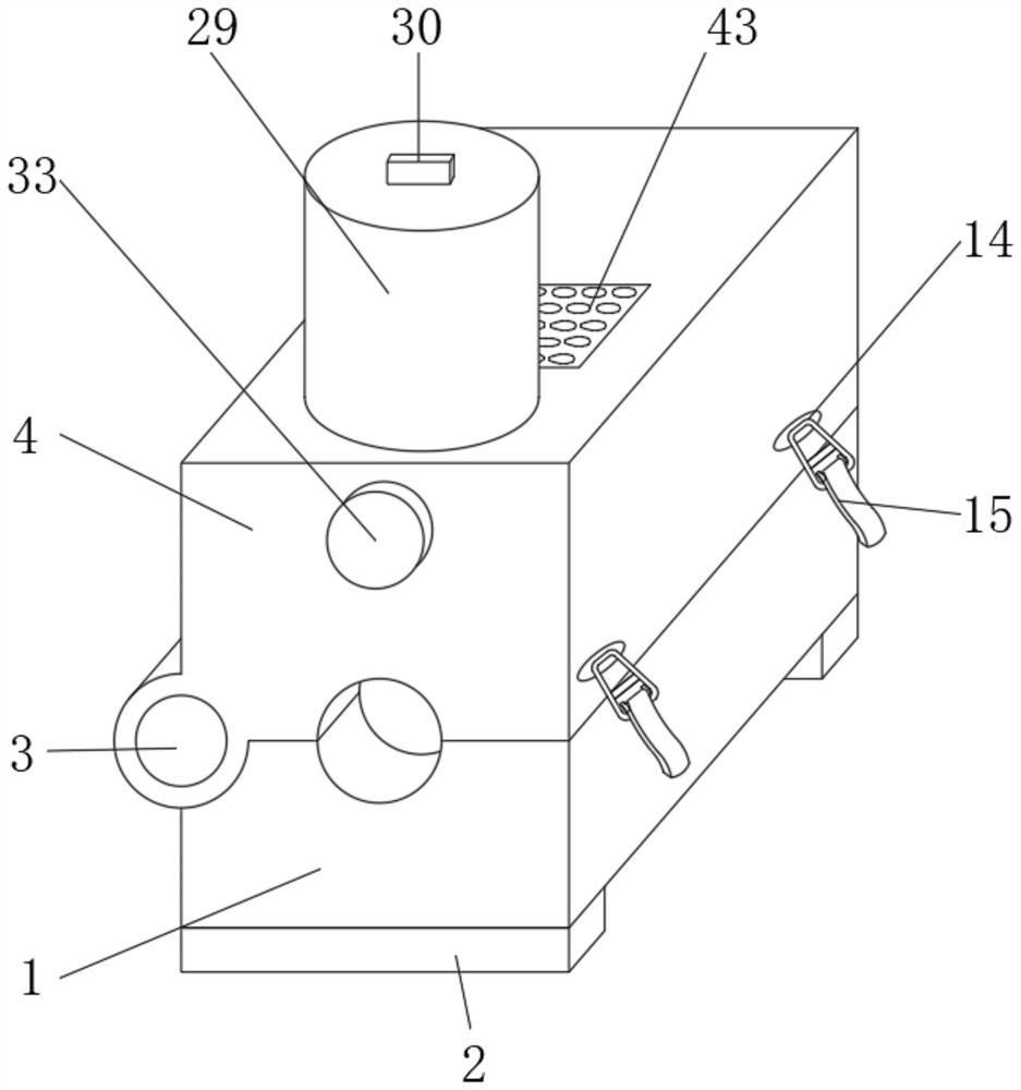
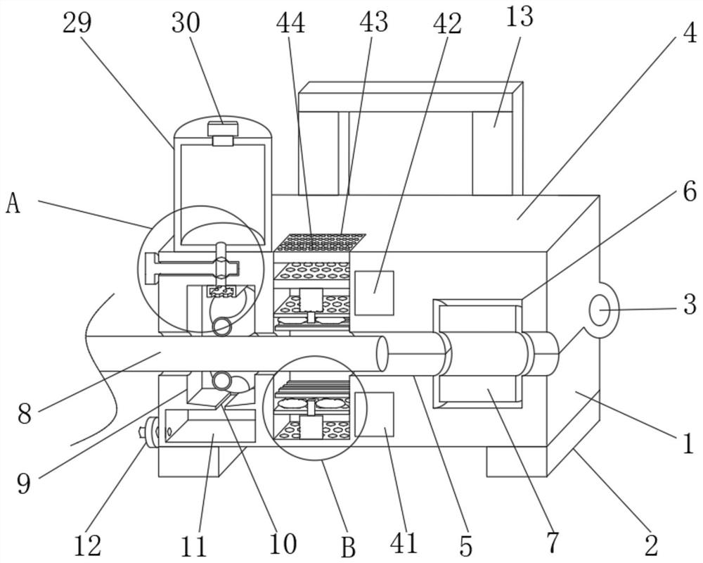
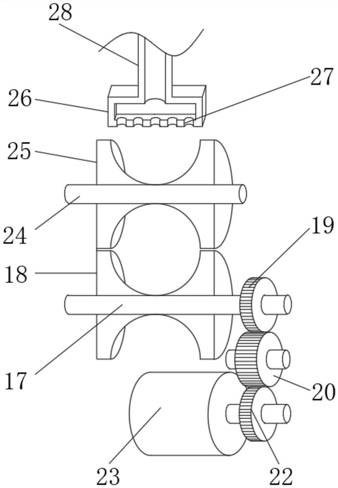
[0036] like Figure 1-5 As shown, a substation copper wire anticorrosion treatment equipment includes a base plate 1, the left and right sides of the bottom of the base plate 1 are symmetrically fixedly connected with support blocks 2, and the top and rear side of the base plate 1 are connected with a top cover 4 through a fixed shaft 3. The cover 4 is arranged directly above the bottom plate 1, and the bottom of the top cover 4 is provided with a copper wire groove 5, which is set in a semicircle shape, and the position of the copper wire groove 5 at the bottom of the top cover 4 and the copper wire groove 5 at the top of the bottom plate 1 Correspondingly, and combined into a circular groove, the bottom right side of the top cover 4 is provided ...


PUM


Abstract

The invention discloses anti-corrosion treatment equipment for for copper wire connection of a transformer substation and an operation method thereof. The anti-corrosion treatment equipment comprises a bottom plate, supporting blocks are symmetrically and fixedly connected to the left side and the right side of the bottom of the bottom plate, a top cover is rotationally connected to the rear side of the top of the bottom plate through a fixing shaft, and a copper wire groove is formed in the center of the top of the bottom plate; and a limiting groove is formed in the right side of the top of the bottom plate, a protective cover is arranged in the middle of the limiting groove, a copper wire is arranged in the middle of the copper wire groove, a collecting groove is formed in the left side of the top of the bottom plate, and a leakage hole is formed in the bottom of an inner cavity of the collecting groove. According to the anti-corrosion treatment equipment for copper wire connection of the transformer substation and the operation method thereof, the arranged collecting groove is matched with a first rotating rod, a first brushing roller, a driven gear, a transmission gear, a limiting rolling shaft, a driving gear and a first engine, so that the copper wire can automatically move in the copper wire groove at a constant speed, and the coating on the surface of the copper wire is more uniform.

Description

technical field [0001] The invention relates to the field of anti-corrosion treatment of copper wires connected to substations, in particular to anti-corrosion treatment equipment for copper wires connected to substations and an operation method thereof. Background technique [0002] The substation refers to the place where the voltage and current are transformed, received and distributed in the power system. The substation in the power plant is a step-up substation. Its function is to boost the power generated by the generator and feed it to the high-voltage power grid. Due to the complex environment of the substation, corrosion problems at the copper wires of the substation are often caused by problems such as humidity and harsh environment. In order to ensure the long-term stable operation and safety of the substation, it is necessary to strengthen the anti-corrosion treatment of the copper wires. The existing anti-corrosion treatment The equipment cannot carry out anti-c...

Claims


Application Information

Patent Timeline
Patent Type & Authority Applications(China)
IPC IPC(8): B05C9/14B05C1/08B05D3/04B05C13/02B05C15/00
CPCB05C9/14B05C1/0813B05C1/08B05D3/0413B05C13/02B05C15/00Y02P70/10
Inventor 蒋科彭风王臻朱峰杨柳莫志剑毕超
Owner SUWEN ELECTRIC ENERGY TECH
Learn More