


Quick Research
Generate reliable direction feasibility study reports for your R&D in just a few steps.

Technical Q&A
Discover and master advanced knowledge NOW. Basics, ideas, possibilities, all at once.

Find Solutions
As an expert in R&D theories, this can generate solutions to your technical problems instantly.

Evaluate Feasibility
Analyze your overall solution with one click, know your potential R&D risks in advance.

Monitor Landscape
Get weekly tech updates, stay abreast of the latest tech innovations and key insights.
A kind of acromioclavicular joint repair device
An acromioclavicular joint and plate technology, applied in the field of acromioclavicular joint repair devices, can solve the problems of inability to produce deformation, iatrogenic damage, large bone removal, etc.
- Summary
- Abstract
- Description
- Claims
- Application Information
AI Technical Summary
Problems solved by technology
Method used
Image


Examples
Embodiment 1
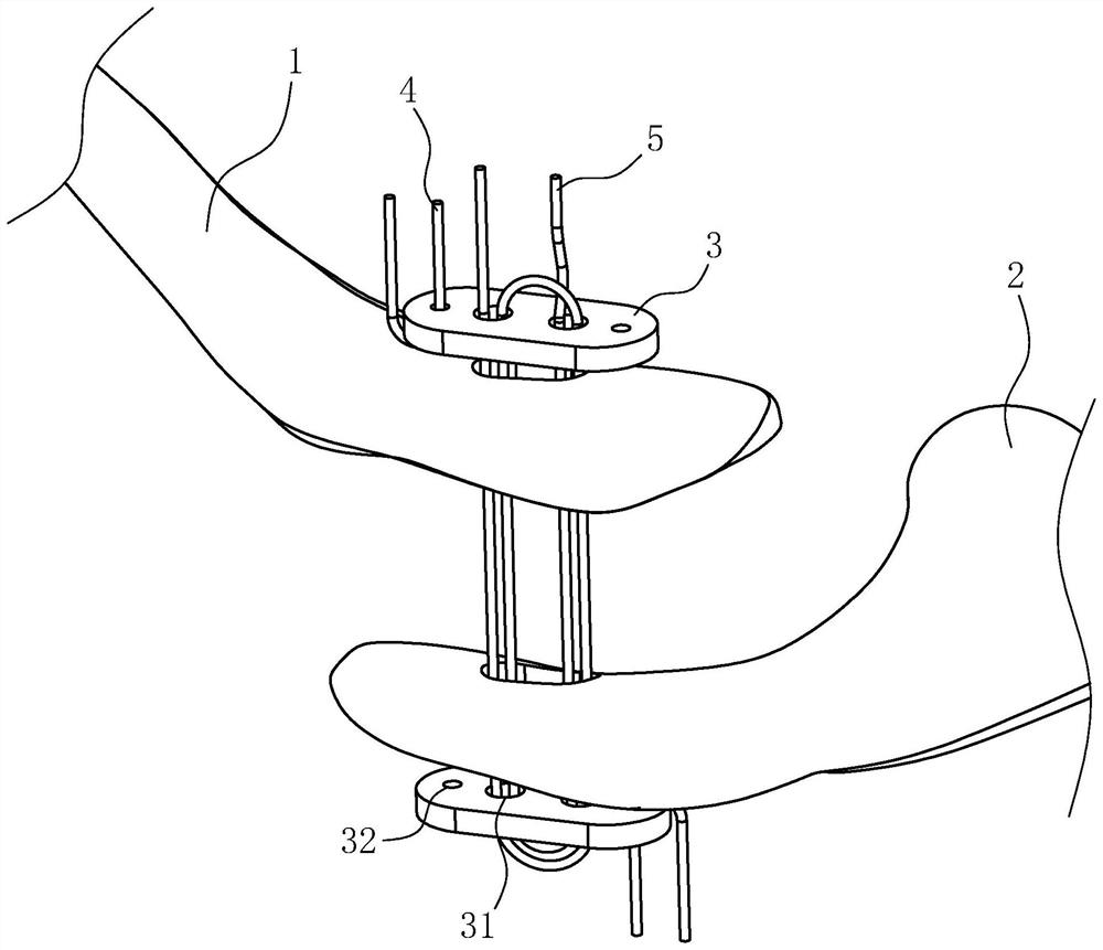
[0045] refer to figure 2 , the application provides an acromioclavicular joint repair device, comprising a first loop plate member 6 made of elastic material and a second loop plate member 7 made of elastic material; the first loop plate member 6 and the second loop plate member 7 A tail line 5 is arranged between the 7, and when the tail line 5 is pulled, the first loop board member 6 and the second loop board member 7 can move toward each other in a direction close to each other; The shape is annular and the structure of the first loop plate member 6 is an inner hollow tubular structure; the shape and structure of the second loop plate member 7 and the first loop plate member 6 are the same, and the difference between the two is only the difference in the installation position, The details are not repeated here; the area enclosed by the inner circle contour of the first flap member 6 and the area enclosed by the inner circle outline of the second flap member 7 form the defo...
Embodiment 2
[0056] refer to Image 6 , the difference between this embodiment and the first embodiment is that the first loop plate member 6 is provided with a first thread hole 65 and a second thread hole 66 distributed along the circumferential direction of the first loop plate member 6, and the second loop plate The member 7 is provided with a third threading hole 75 and a fourth threading hole 76 distributed along the circumferential direction of the second flap member 7 at intervals.
[0057] In this embodiment, the first threading hole 65 and the second threading hole 66 are respectively opened on both sides of the first loop plate member 6 and communicate with the inside of the first loop plate member 6; the third threading hole 75 and the fourth threading hole 76 are respectively opened on both sides of the second loop board member 7 and communicate with the inside of the second loop board member 7 .
[0058] The common point of the routing paths of the two tail wires 5 is that t...
Embodiment 3
[0061] refer to Figure 7 , the difference between this embodiment and the second embodiment is that the coiling method of the tail wire 5 on the first loop board member 6 and the second loop board member 7 is different.
[0062] It is further explained that a plurality of through holes distributed along the circumferential direction of the first loop board member 6 are provided on the inner side and the outer side of the first loop board member 6, and after the tail wire 5 enters the inside of the first loop board member 6, Passing through these through holes in turn enables the tail wire 5 to reciprocately penetrate into and out of the first loop member 6;
[0063] In this way, the number of connection parts between the first loop board member 6 and the tail wire 5 and between the second loop board member 7 and the tail wire 5 is increased. When the tail wire 5 is inside the first loop board member 6 and the second loop board When the inside of the piece 7 shrinks and becom...
PUM
 Abstract
Description
Claims
Application Information
 - R&D Engineer
- R&D Manager
- IP Professional
- Industry Leading Data Capabilities
- Powerful AI technology
- Patent DNA Extraction
Browse by: Latest US Patents, China's latest patents, Technical Efficacy Thesaurus, Application Domain, Technology Topic, Popular Technical Reports.
© 2024 PatSnap. All rights reserved.Legal|Privacy policy|Modern Slavery Act Transparency Statement|Sitemap|About US| Contact US: help@patsnap.com