


Quick Research
Generate reliable direction feasibility study reports for your R&D in just a few steps.

Technical Q&A
Discover and master advanced knowledge NOW. Basics, ideas, possibilities, all at once.

Find Solutions
As an expert in R&D theories, this can generate solutions to your technical problems instantly.

Evaluate Feasibility
Analyze your overall solution with one click, know your potential R&D risks in advance.

Monitor Landscape
Get weekly tech updates, stay abreast of the latest tech innovations and key insights.
Vertical sludge drying machine
A sludge drying, vertical technology, applied in sludge treatment, water/sludge/sewage treatment, dehydration/drying/concentrated sludge treatment, etc. , affecting sludge treatment and other issues, to achieve the effect of shortening drying time, improving drying efficiency and uniform heating
- Summary
- Abstract
- Description
- Claims
- Application Information
AI Technical Summary
Problems solved by technology
Method used
Image

Examples
Embodiment 1
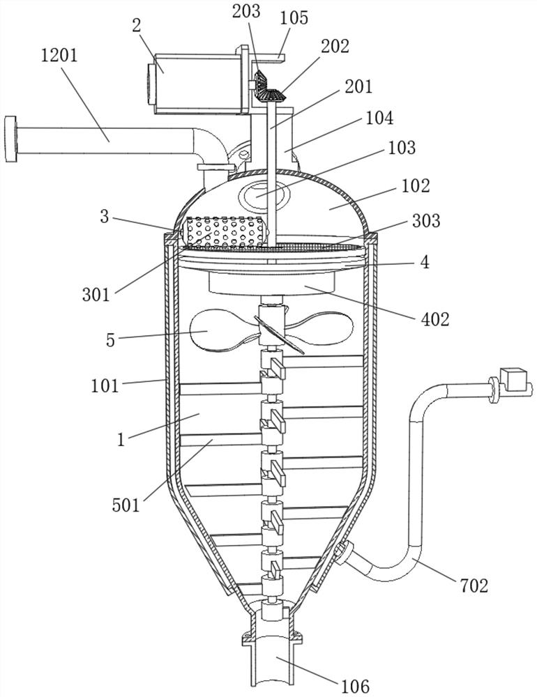
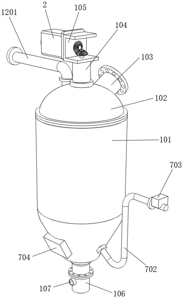
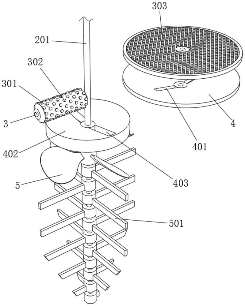
[0032] refer to Figure 1-Figure 5 , a vertical sludge dryer, including a bottom plate 6 and a reactor 1, the inner wall of the reactor 1 is provided with a nano-coating, thereby solving the problem of drying highly viscous sludge, and the outer surface of the reactor 1 is socketed There is a shell 101, and an oil-conducting layer is arranged between the shell 101 and the reactor 1. The top of the reactor 1 is fixed with a cover 102 by bolts. The top of the cover 102 is inserted with a feed pipe 103. The inner wall of the reactor 1 is The top of the top is fixed with a filter plate 303 and the first conical plate 4 by bolts, and the sludge falls on the filter plate 303 for filtering, and the solid particle impurities contained in the sludge are filtered, and the filter plate 303 and the first conical plate 4 is set up and down, the upper surface of the first cone-shaped plate 4 is provided with a feeding port 401, the upper surface of the cover body 102 is fixed with a support...
Embodiment 2
[0037] refer to Figure 6-Figure 7 , a vertical sludge dryer, including one end of the feed pipe 103 connected with a feed hopper 14 through a flange, the inner wall of one side of the feed hopper 14 is fixed with a baffle 1401 by bolts, and the top of the bottom plate 6 is fixed by bolts There is a liquid collection tank 13, one side of the liquid collection tank 13 is plugged with a fixed pipe 1402, and the top of the fixed pipe 1402 is provided with a water filter layer 1403, and in the sludge conveying hopper 14, the sludge will be received by the baffle 1401 Part of the moisture in the sludge is squeezed out, and the squeezed water falls into the fixed pipe 1402 after being filtered by the filter water layer 1403, and finally falls into the liquid collection tank 13 for centralized collection.
[0038] The working principle of this embodiment: when in use, the sludge is conveyed from the feed hopper 14, and in the feed hopper 14, the sludge is squeezed by the baffle 1401,...
PUM
 Abstract
Description
Claims
Application Information
 - R&D Engineer
- R&D Manager
- IP Professional
- Industry Leading Data Capabilities
- Powerful AI technology
- Patent DNA Extraction
Browse by: Latest US Patents, China's latest patents, Technical Efficacy Thesaurus, Application Domain, Technology Topic, Popular Technical Reports.
© 2024 PatSnap. All rights reserved.Legal|Privacy policy|Modern Slavery Act Transparency Statement|Sitemap|About US| Contact US: help@patsnap.com