Transmission mechanism
A transmission mechanism and sliding transmission technology, applied in driving devices, automatic control devices, metal processing machinery parts, etc., can solve the problems of inability to directly process elliptical curved surfaces, difficult to meet high requirements for machining accuracy, and difficult to guarantee contour accuracy.
- Summary
- Abstract
- Description
- Claims
- Application Information
AI Technical Summary
Problems solved by technology
Method used
Image
Examples
Embodiment 1
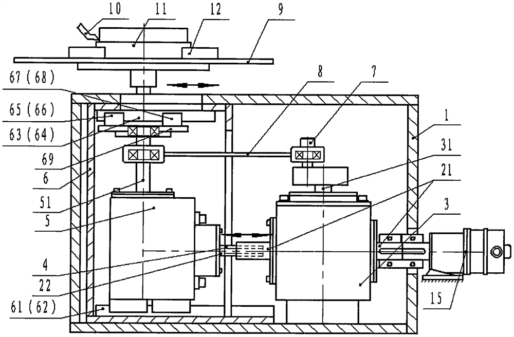
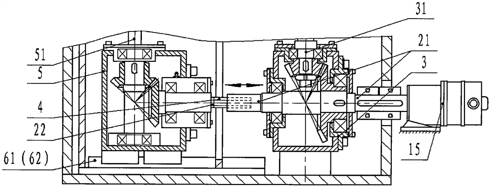
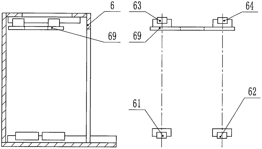
[0071] as attached figure 1 , attached image 3 shown, and see the attached figure 2 , attached Figure 4 , attached Figure 5 , attached Figure 7 , the embodiment of the present invention provides a transmission mechanism, including a box body 1, a first power shaft 21, a second power shaft 22, a steering gearbox A3, a first power output shaft 31, a spline transmission shaft 4, a steering gearbox B5, the second power output shaft 51, guide rail frame 6, linear guide rail 61, linear guide rail 62, linear guide rail 63, linear guide rail 64, slider 65, slider 66, slider 67, slider 68, connecting plate 69, eccentric Shaft 7, connecting rod 8, table 9, tool 10, workpiece 11, fixture 12, crankshaft 13, power source 15.
[0072] The steering gearbox A3 is fixedly installed on the box body 1, and the first power shaft 21 and the first power output shaft 31 perpendicular to each other are arranged on it, and the eccentric shaft 7 or the crankshaft 13 is installed at the end of...
Embodiment 2
[0087] as attached Figure 8 , attached image 3 shown, and see the attached Figure 4 , attached Figure 5 , with Figure 7 , attached Figure 9 , the embodiment of the present invention provides a transmission mechanism, including a box body 1, a first power shaft 21, a second power shaft 22, a steering gearbox A3, a first power output shaft 31, a spline transmission shaft 4, a steering gearbox B5, the second power output shaft 51, guide rail frame 6, linear guide rail 61, linear guide rail 62, linear guide rail 63, linear guide rail 64, slider 65, slider 66, slider 67, slider 68, connecting plate 69, eccentric Shaft 7, connecting rod 8, workbench 9, cutter 10, workpiece 11, fixture 12, crankshaft 13, power distribution box 14, power source 15.
[0088] On the basis of Embodiment 1, the difference between this embodiment and Embodiment 1 is that in Embodiment 1, the power source is connected to the steering gearbox A3, and the power is first transmitted to the steering ...
Embodiment 3
[0091] On the basis of Embodiment 1 and Embodiment 2 of the present invention, this embodiment does not limit whether the power source is the same power source, does not limit the power transmission mode (series or parallel), and only needs to ensure that the first power connected to the power transmission mechanism The output shaft 31 and the second power output shaft 51 are parallel to each other with a speed ratio of 2:1, and keep moving synchronously according to the speed ratio of 2:1.
[0092] as attached Figure 10 shown, and see the attached Figure 7 , the embodiment of the present invention further provides a transmission mechanism, including a first power output shaft 31, a second power output shaft 51, an eccentric shaft 7, a connecting rod 8, a worktable 9, a tool 10, a workpiece 11, a fixture 12, Crankshaft 13, power transmission mechanism 16.
[0093] The power transmission mechanism 16 is provided with a first power output shaft 31 and a second power output s...
PUM
 Abstract
Description
Claims
Application Information
 - R&D Engineer
- R&D Manager
- IP Professional
- Industry Leading Data Capabilities
- Powerful AI technology
- Patent DNA Extraction
Browse by: Latest US Patents, China's latest patents, Technical Efficacy Thesaurus, Application Domain, Technology Topic, Popular Technical Reports.
© 2024 PatSnap. All rights reserved.Legal|Privacy policy|Modern Slavery Act Transparency Statement|Sitemap|About US| Contact US: help@patsnap.com


