
Torque sensor interface circuit for EPS system

A technology of torque sensor and interface circuit, applied in the field of torque sensor interface circuit, can solve problems such as safety accidents, increase the computing power of single-chip microcomputer, and poor driving experience, and achieve the effect of improving response speed, solving real-time problems, and expanding measurement range.

Pending Publication Date: 2021-10-15
湖南东嘉智能科技有限公司
View PDF5 Cites 0 Cited by
  • Summary
  • Abstract
  • Description
  • Claims
  • Application Information

AI Technical Summary

Problems solved by technology

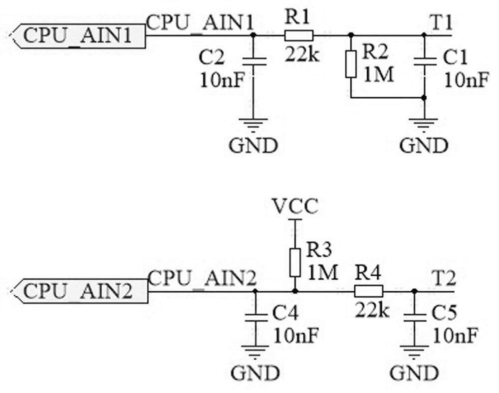
[0005] 1. After the torque signal is processed by the RC filter of the interface circuit, the signal will have a certain delay, but the EPS system has high requirements for real-time performance, and the delay of the torque signal will affect the followability of the system, giving the driver My subjective feeling is that after turning the steering wheel, the wheels turn not in time, the driving experience is not good, and it may lead to safety accidents during emergency avoidance
In order to solve this problem, it is necessary to add the corresponding advanced algorithm in the software processing, and do closed-loop processing together with the input torque signal. In this way, it is necessary to increase the computing power of the single-chip microcomputer, and use a more advanced single-chip microcomputer to increase the complexity of the software.
But this does not fundamentally solve the real-time problem of the system, but only improves;
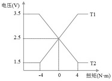
[0006] 2. The torque sensor only has a range of 1V from the midpoint position (2.5V) to the limit position (3.5V or 1.5V). The range is too narrow, and the small adjustment of the steering wheel hand force cannot be responded to by the EPS system, thus showing The accuracy of the system is not high

Method used


Image

  • Torque sensor interface circuit for EPS system
  • Torque sensor interface circuit for EPS system
  • Torque sensor interface circuit for EPS system

Examples


Embodiment Construction

[0021] In order to facilitate the understanding of those skilled in the art, the present invention will be further described below in conjunction with the embodiments and accompanying drawings, and the contents mentioned in the embodiments are not intended to limit the present invention.

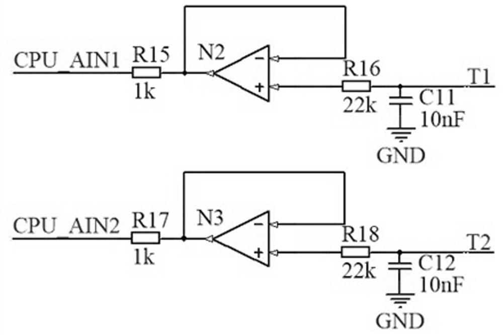
[0022] A torque sensor interface circuit for EPS system, used for leading compensation of torque signal, such as Figure 4 As shown, it includes: a first interface circuit for collecting T1 signals, a second interface circuit for collecting T2 signals, and a lead compensation circuit for collecting PD signals.

[0023] Specifically, the first interface circuit is connected to the lead compensation circuit, and the lead compensation circuit includes a differential amplifier circuit. The differential amplifier circuit is composed of an operational amplifier N1, a resistor R8, a resistor R5, and a resistor R6. R6 is connected in series to the inverting input terminal of the operational amplifie...


PUM


Abstract

The invention provides a torque sensor interface circuit for an EPS system, relates to the technical field of automotive electronics, and is used for carrying out advanced compensation on torque signals, the interface circuit comprises a first interface circuit for collecting T1 signals, a second interface circuit for collecting T2 signals and a lead compensation circuit for collecting PD signals; compared with an interface circuit in the prior art, the interface circuit has the advantages that the lead compensation circuit is added, the PD signals collected through the lead compensation circuit are ahead of real torque signals, the measurement range of the torque signals is expanded, fine processing of the torque signals is facilitated, the response speed of the EPS system to the torque signals is further increased, and the real-time problem of the EPS system is fundamentally solved.

Description

technical field [0001] The invention relates to the technical field of automobile electronics, in particular to a torque sensor interface circuit for an EPS system. Background technique [0002] At present, the automobile industry is in a period of rapid development. As an indispensable part of automobiles, EPS (Electric Power Steering) is the development direction of automobile steering systems. The system directly provides steering assist by the electric power assist motor, which saves the power steering oil pump, hose, hydraulic oil, conveyor belt and pulley installed on the engine necessary for the hydraulic power steering system, which not only saves energy, but also protects the environment. In addition, it also has the characteristics of simple adjustment, flexible assembly and power steering under various conditions. [0003] The vehicle-mounted torque sensor is composed of simple electronic circuits. The existing torque sensor interface circuit is as follows: figu...

Claims


Application Information

Patent Timeline
Patent Type & Authority Applications(China)
IPC IPC(8): G01L5/22
CPCG01L5/22
Inventor 刘锴林联伟高明
Owner 湖南东嘉智能科技有限公司
Learn More