
Packaging bag sealing device

A sealing device, packaging bag technology, applied in packaging sealing/fastening, packaging, transportation packaging, etc., can solve problems such as reducing equipment service life, component position deviation, processing quality impact, etc., to improve quality and speed, friction The effect of reducing force and reducing energy consumption

Active Publication Date: 2021-10-15
南通永辉自动化科技有限公司
View PDF8 Cites 1 Cited by
  • Summary
  • Abstract
  • Description
  • Claims
  • Application Information

AI Technical Summary

Problems solved by technology

[0005] Aiming at the deficiencies of the prior art, the present invention provides a packaging bag sealing device, which solves the problem that the existing packaging bag sealing device is prone to misalignment of components during use, resulting in tilting of the sealing and leakage of seals. The processing quality is easily affected, and at the same time, the position of the components is accurate to avoid mutual wear and reduce the service life of the equipment

Method used


Image

  • Packaging bag sealing device
  • Packaging bag sealing device
  • Packaging bag sealing device

Examples


Embodiment 1

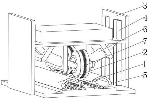
[0044] see Figure 1-5 , the present invention provides a technical solution: a packaging bag sealing device, specifically comprising:

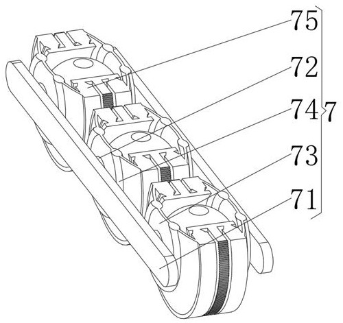
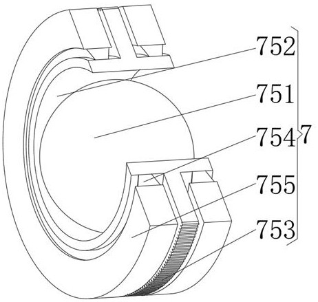
[0045] Base 1, the base 1 has a square seat plate, and a conveying device 2 installed in the middle of the top of the square seat plate, and a support frame plate 3 installed in the middle of the outer walls on both sides of the square seat plate, and installed on the support frame plate 3 close to The limiting concave plate 4 on one side of the conveying device 2, and the lifting adjustment column 5 installed at the bottom of the inner cavity of the limiting concave plate 4, and the temperature control device 6 installed on the top of the lifting adjusting column 5, and installed on the temperature control device 6 The sealing device 7 in the middle position restricts the running track of the equipment components through the setting of the limiting concave plate 4, avoids misalignment and offset during the movement, and protects the equipmen...

Embodiment 2

[0057] see Figure 1-5 On the basis of Embodiment 1, the present invention provides a technical solution: a method for using a packaging bag sealing device, comprising the following steps,

[0058] Step 1: start the driver 28, so that the top conveying wheel 24 is powered to rotate and convey, and use the gravity of the top conveying wheel 24 to attach to the bottom conveying wheel 23;

[0059] Step 2: start the heating coil 66 in the temperature control device 6, so that the heating coil 66 heats the curved curved rod 65;

[0060] Step 3: Start the lifting and adjusting column 5, so that the bearing plate 62 of the temperature control device 6 starts to descend, and drives the positioning partition 63 to move downward until the installation ring plate 755 in the sealing wheel 75 contacts the sealing bottom plate 22 in the conveying device 2 ;

[0061] Step 4: Put the mouth of the packaging bag between the top conveying wheel 24 and the bottom conveying wheel 23, and use the...


PUM


Abstract

The invention discloses a packaging bag sealing device which specifically comprises a base, a limiting concave plate installed at the side, close to a conveying device, of a supporting frame plate, a lifting adjusting column installed at the bottom of an inner cavity of the limiting concave plate and a sealing device body installed in the middle of a temperature control device. The sealing device body comprises a heat conducting frame plate, a heat transfer column mounted at the side, away from the temperature control device, of a strip-shaped plate body, a spherical mounting plate mounted at the side, away from the strip-shaped plate body, of the heat transfer column, a heat insulation ring mounted on the spherical mounting plate and located at the outer side of the heat transfer column, and a sealing wheel mounted at the side, away from the heat transfer column, of the spherical mounting plate. The invention relates to the technical field of packaging machines. An operation track of equipment components is limited through the arrangement of the limiting concave plate, dislocation and deviation in the movement process are avoided, the equipment components are mutually protected, and meanwhile the arrangement of the lifting adjusting column facilitates control over the distance between the components.

Description

technical field [0001] The invention relates to the technical field of packaging machinery, in particular to a packaging bag sealing device. Background technique [0002] The structure of the sealing operation part of the packaging bag sealing machine mainly includes two cross beams moving towards each other, each beam is fixed with a piece of electric heating sealing clip, and each beam is connected with a transmission mechanism that drives it to move back and forth in a straight line. Driven by the transmission mechanism, two pieces of electric heating sealing clips are clamped to each other to seal the plastic packaging bag. [0003] The existing packaging bag sealing device is prone to misalignment of components during use, resulting in tilting of the seal, resulting in leakage, and the processing quality is easily affected. At the same time, the position of the components is accurate to avoid mutual wear and reduce the service life of the equipment. Contents of the in...

Claims


Application Information

Patent Timeline
Patent Type & Authority Applications(China)
IPC IPC(8): B65B51/16
CPCB65B51/16
Inventor 徐永新
Owner 南通永辉自动化科技有限公司
Learn More