An automatic sealing device and method

A sealing device and sealing technology, which are applied to devices and coatings that apply liquid to the surface, can solve problems such as low efficiency, waste of glue consumption, unqualified products, etc., so as to improve the sealing effect and work. Efficiency, the effect of ensuring product quality

Active Publication Date: 2022-05-27
浙江先导热电科技股份有限公司
View PDF6 Cites 0 Cited by
  • Summary
  • Abstract
  • Description
  • Claims
  • Application Information

AI Technical Summary

Problems solved by technology

The conventional process is manual application, which is inefficient and the amount of glue cannot be controlled, resulting in waste of glue used. If the inner cavity of the product is sealed and the temperature rises, it is very easy to cause silicone bubbles to occur, resulting in unqualified products

Method used


Image

  • An automatic sealing device and method
  • An automatic sealing device and method
  • An automatic sealing device and method

Examples


Embodiment 1

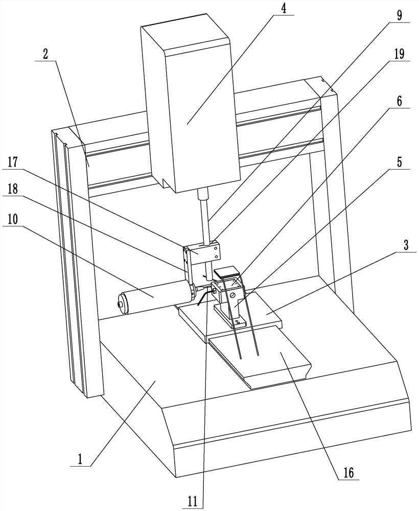
[0031] Example 1: An automatic sealing device (see attached figure 1 , attached figure 2 ), including the worktable 1, the frame 2, the base 3 that can move forward and backward is installed on the worktable, the sliding seat 4 that can move left and right is installed on the frame, and the limit seat 5 is installed on the base. The positioning groove 6 of the sealing product is provided with a number of negative pressure adsorption holes 7 on the bottom surface of the positioning groove, and an air suction cavity is arranged on the limit seat. A heater 8 is installed at the bottom of the positioning groove on the seat to make the temperature at the bottom of the positioning groove higher than the ambient temperature; a liftable rotating shaft 9 is installed on the sliding seat, and a glue gun 10 is installed on the rotating shaft. The end of the rubber head is placed on the axis of rotation of the shaft.

[0032] The positioning groove has a rectangular structure, and the ...

Embodiment 2

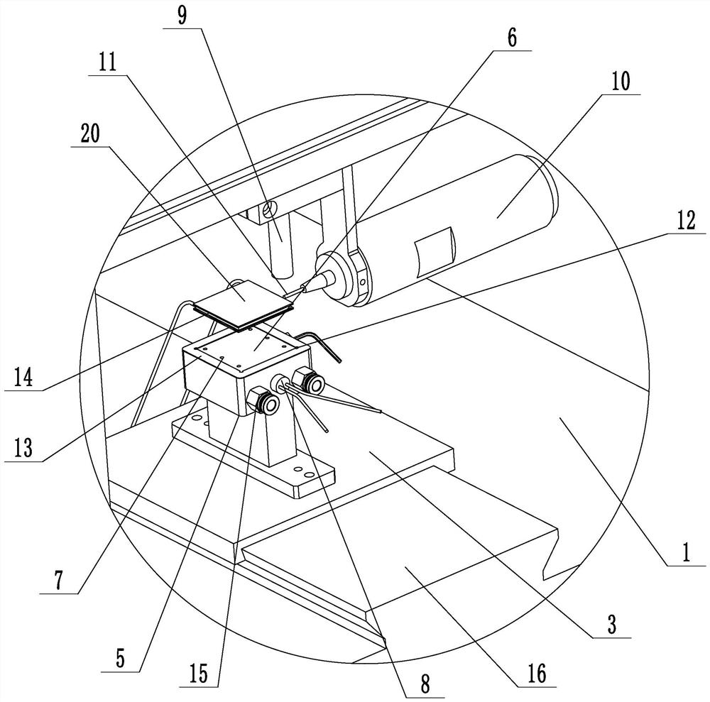
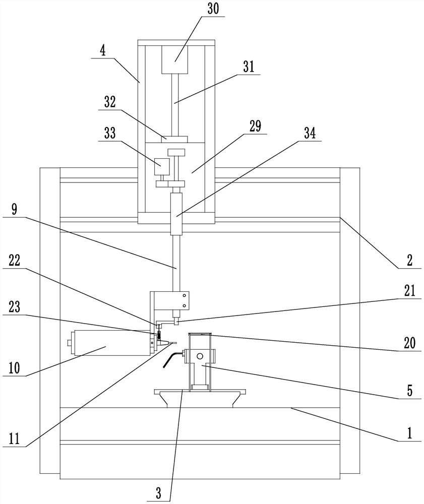
[0043] Example 2: An automatic sealing device (see attached image 3 , attached Figure 4 ), its features are similar to those in Embodiment 1, the main difference is that in this implementation, the sliding seat is connected with a vertical rod 21, the rotating shaft is in a hollow tubular structure, the vertical rod and the rotating shaft are movably sleeved together, and the lower end of the vertical rod extends out of the rotating shaft, and the vertical rod The lower end is connected with a push guide bar 22; the glue gun is connected to an impact cylinder 23 near the glue discharge head, and the lower end of the impact cylinder is communicated with the glue gun. Tightly connect the positioning pin 27, the upper end of the top rubber piston abuts on the positioning pin, the return spring abuts between the positioning pin and the pressurizing piston, the pressurizing piston is connected to the top rod 28, and pushes the lower surface of the guide bar from the middle to bot...


PUM


Abstract

The invention discloses an automatic sealing device and method, aiming to solve the problem of low sealing efficiency of sealing products. The invention includes a workbench and a frame. A base that can move back and forth is installed on the workbench. A sliding seat that can move left and right is installed on the frame. A limit seat is installed on the base. The bottom surface of the positioning groove is provided with a number of negative pressure adsorption holes, and the limit seat is provided with a suction chamber. The heater makes the temperature at the bottom of the positioning groove higher than the ambient temperature; a movable shaft is installed on the sliding seat, and a glue gun is installed on the shaft. The glue gun is equipped with a glue head, and the end of the glue head is placed on the rotation axis of the shaft. . This automatic sealing device can automatically seal the ceramic plate type products, which improves the work efficiency, and there will be no silicone bubbles at the sealing position, which ensures the product quality.

Description

technical field [0001] The present invention relates to a glue sealing technology, and more particularly, to an automatic glue sealing device and method. Background technique [0002] At present, after the ceramic flat product is assembled, the material between the upper and lower ceramic substrates needs to be completely sealed with silica gel, but at the same time, the two lead-out wires should be avoided. The conventional process is manual application, which is inefficient, and the amount of glue cannot be controlled, resulting in waste of the amount of glue used. If the inner cavity of the product is sealed, if the temperature rises, it is very easy to cause the phenomenon of silica gel bubbling, resulting in unqualified products. SUMMARY OF THE INVENTION [0003] In order to overcome the above deficiencies, the present invention provides an automatic sealing device and method, which can automatically seal ceramic flat products, improve work efficiency, and the phenome...

Claims


Application Information

Patent Timeline
Patent Type & Authority Patents(China)
IPC IPC(8): B05C5/02B05C11/10B05C13/02B05D1/26
CPCB05C5/02B05C11/10B05C13/02B05D1/26
Inventor 贾向军
Owner 浙江先导热电科技股份有限公司
Why Eureka
Try Eureka