
Optical cable anomaly detection method and device

An anomaly detection and optical cable technology, applied in electromagnetic wave transmission systems, electrical components, transmission systems, etc., can solve the problems of optical cable fault detection and low accuracy, and achieve the effect of improving the accuracy rate

Pending Publication Date: 2021-10-08
INFORMATION & COMM COMPANY OF QINGHAI ELECTRIC POWER +2
View PDF0 Cites 7 Cited by
  • Summary
  • Abstract
  • Description
  • Claims
  • Application Information

AI Technical Summary

Problems solved by technology

[0008] The embodiment of the present invention provides a method and device for detecting an abnormality of an optical cable, so as to at least solve the technical problem of low accuracy of optical cable fault detection in the related art

Method used


Image

  • Optical cable anomaly detection method and device
  • Optical cable anomaly detection method and device
  • Optical cable anomaly detection method and device

Examples


Embodiment Construction

[0034] In order to enable those skilled in the art to better understand the solutions of the present invention, the following will clearly and completely describe the technical solutions in the embodiments of the present invention in conjunction with the drawings in the embodiments of the present invention. Obviously, the described embodiments are only It is an embodiment of a part of the present invention, but not all embodiments. Based on the embodiments of the present invention, all other embodiments obtained by persons of ordinary skill in the art without making creative efforts shall fall within the protection scope of the present invention.

[0035] It should be noted that the terms "first" and "second" in the description and claims of the present invention and the above drawings are used to distinguish similar objects, but not necessarily used to describe a specific sequence or sequence. It is to be understood that the data so used are interchangeable under appropriate ...


PUM


Abstract

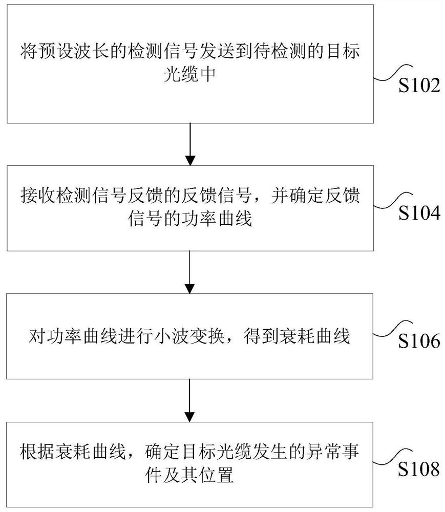
The invention discloses an optical cable anomaly detection method and device. The method comprises the following steps: sending a detection signal with a preset wavelength to a to-be-detected target optical cable; receiving a feedback signal fed back by the detection signal, and determining a power curve of the feedback signal; performing wavelet transformation on the power curve to obtain an attenuation curve; and according to the attenuation curve, determining the abnormal event of the target optical cable and the position thereof. According to the invention, the technical problem of low accuracy of optical cable fault detection in the prior art is solved.

Description

technical field [0001] The invention relates to the field of optical cable detection, in particular to an optical cable abnormality detection method and device. Background technique [0002] With the rapid development of optical fiber networks, the complexity of the network is increasing day by day, and the management and maintenance of optical fiber physical networks are becoming increasingly heavy. Timely detection of fiber optic network failures and ensuring the security and stability of the fiber optic physical network are the current focus of network maintenance. Therefore, there is an urgent need to establish a fiber optic monitoring system that organically combines fiber optic monitoring, warning, fault analysis, positioning, and line maintenance to provide guarantees for the safe and efficient operation of fiber optic networks. [0003] The main detection purpose of optical fiber monitoring is to detect the singular point or fault point position in the optical fiber...

Claims


Application Information

Patent Timeline
Patent Type & Authority Applications(China)
IPC IPC(8): H04B10/071H04B10/077
CPCH04B10/071H04B10/0775H04B10/0771
Inventor 孙少华杨林慧刘永胜长全平
Owner INFORMATION & COMM COMPANY OF QINGHAI ELECTRIC POWER
Learn More