A Block Matrix Storage Method in Circuit Simulation
A block-matrix and circuit simulation technology, applied in electrical digital data processing, instruments, complex mathematical operations, etc., can solve problems such as excessive data volume, slow speed, and difficulty in parallel processing, achieving accelerated calculation and reduced requirements , the effect of improving computing efficiency
- Summary
- Abstract
- Description
- Claims
- Application Information
AI Technical Summary
Problems solved by technology
Method used
Image
Examples
Embodiment 1
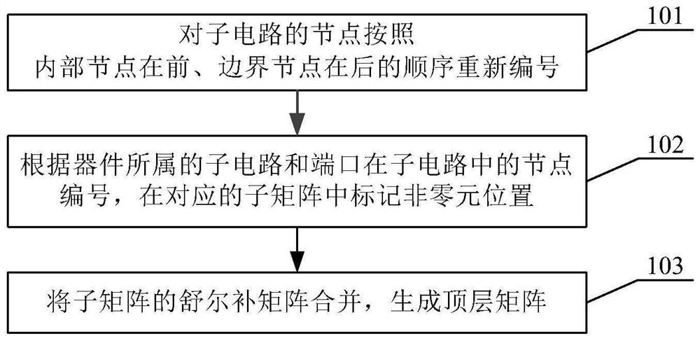
[0033] Figure 1 For a flowchart of a block matrix storage method in circuit simulation of the present invention, reference will be made below Figure 1 , a detailed description of the block matrix storage method in circuit simulation of the present invention.
[0034] First, in step 101, the circuit nodes are renumbered according to the circuit division, a new sub-matrix is established.
[0035] In an embodiment of the present invention, the nodes of each subcircuit are renumbered according to the rules of the internal node in front and the boundary node in the back.
[0036] In an embodiment of the present invention, all nodes are renumbered in the order of traversing the internal nodes of each subcircuit, and then traversing the boundary nodes.
[0037] Each subcircuit builds a new sub-matrix using the connected nodes according to the relative order of the renumbered nodes.
[0038] In step 102, iterates through all the devices, according to the node number of the subcircuit and p...
Embodiment 2
[0051] The following in conjunction with a specific embodiment of the circuit simulation of the present invention in the block matrix storage method is further described.
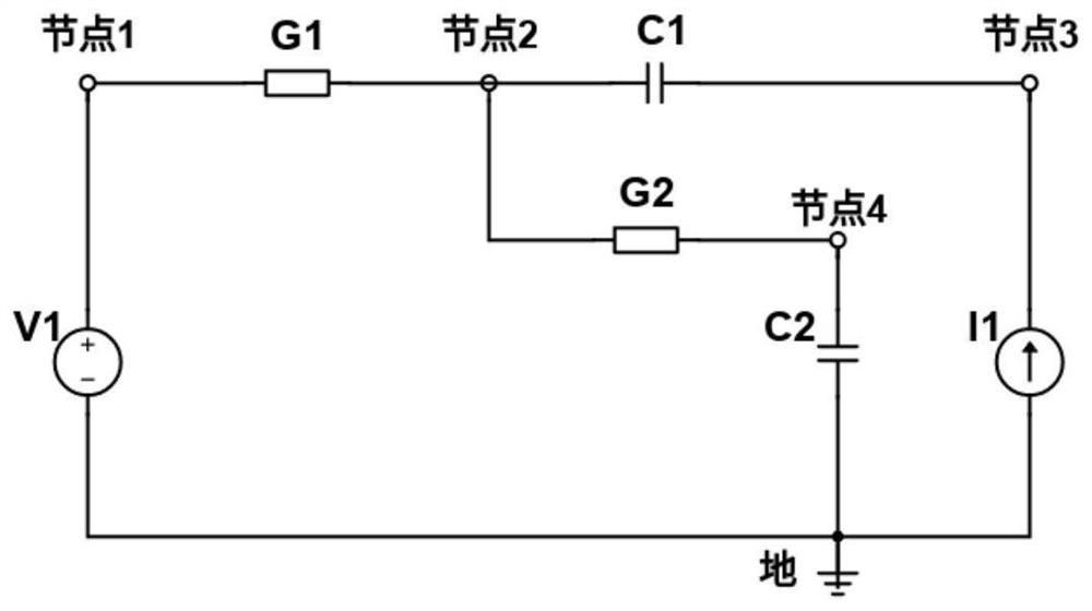
[0052] Figure 2 For a circuit diagram according to one embodiment of the present invention, using the block matrix storage method of the present invention, pair Figure 2 The circuit in the implementation of the calculation, which can be performed as follows:
[0053] Suppose node 2 and node 4 are boundary nodes; nodes 1, V1, G1, G2, and C2 belong to the first subcircuit, and nodes 3, C1, and I1 belong to the second subcircuit.
[0054] In step 1, the circuit nodes are renumbered by circuit division, following the rules of internal nodes first and boundary nodes behind. Each subcircuit numbers the connected nodes in this order, resulting in Figure 3 The numbered table in .
[0055] In step 2, iterate over all the devices, each adding coefficients to the matrix to which it belongs. get Figure 4 , Figure 5 2 subm...
PUM
 Abstract
Description
Claims
Application Information
 - R&D
- Intellectual Property
- Life Sciences
- Materials
- Tech Scout
- Unparalleled Data Quality
- Higher Quality Content
- 60% Fewer Hallucinations
Browse by: Latest US Patents, China's latest patents, Technical Efficacy Thesaurus, Application Domain, Technology Topic, Popular Technical Reports.
© 2025 PatSnap. All rights reserved.Legal|Privacy policy|Modern Slavery Act Transparency Statement|Sitemap|About US| Contact US: help@patsnap.com


