Vacuum microwave smelting device

A vacuum microwave and microwave technology, which is used in stirring devices, crucible furnaces, furnaces, etc., can solve problems such as affecting the melting effect and hot spots of the working medium, and achieve the effects of shortening the process time, uniform statistics, and high safety performance.

Pending Publication Date: 2021-10-08
INST OF APPLIED ELECTRONICS CHINA ACAD OF ENG PHYSICS +1
View PDF12 Cites 0 Cited by
  • Summary
  • Abstract
  • Description
  • Claims
  • Application Information

AI Technical Summary

Problems solved by technology

At present, the design of the furnace body of the microwave industrial application equipment used is mostly based on the resonant cavity theory design. The spatial distribution of the electromagnetic field in the furnace body designed by the resonant cavity theory is strongly related to the microwave frequency. The size of the furnace body is limited by the microwave wavelength, and the structure of the furnace body is determined. Afterwards, the spatial distribution of the electromagnetic field is determined, and it is easy to appear "hot spots" in the working fluid, which will affect the melting effect

Method used


Image

  • Vacuum microwave smelting device
  • Vacuum microwave smelting device
  • Vacuum microwave smelting device

Examples


Embodiment 1

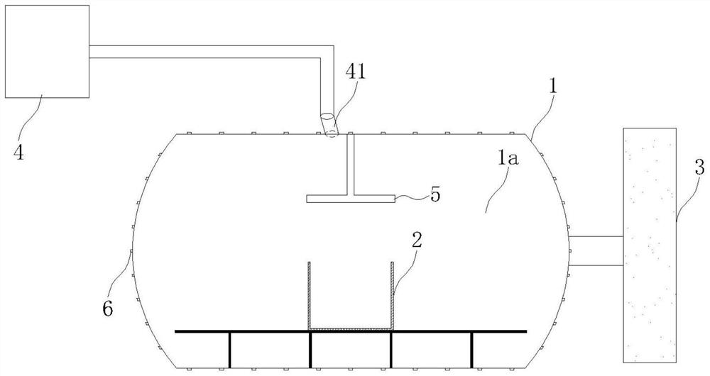
[0053] Such as figure 1 , 4 As shown, a vacuum microwave smelting device in this embodiment includes a horizontal furnace body 1 with a cavity 1a, a microwave gap is arranged on the furnace body 1, a support frame 11 is set in the cavity 1a, and a support frame (11) is set Insulation board 21; furnace body 1 consists of hatch, hatch head, hatch flange, door handle, observation window, cylinder, hinge, locking mechanism, rotating mechanism, microwave feeder and corresponding interface flanges Each interface on the furnace body 1 is vacuum-sealed and electromagnetically shielded; the diameter of the cavity 1a is 1200mm, and the length of the furnace body 1 is 1500mm;

[0054] A silicon carbide crucible 2 is arranged on a heat shield 21, and an insulation layer 22 is arranged outside the crucible 2, and the temperature safety of the furnace body 1 is ensured by the fact that the crucible 2 does not directly contact the furnace body 1;

[0055] The vacuum system 3 communicates ...

Embodiment 2

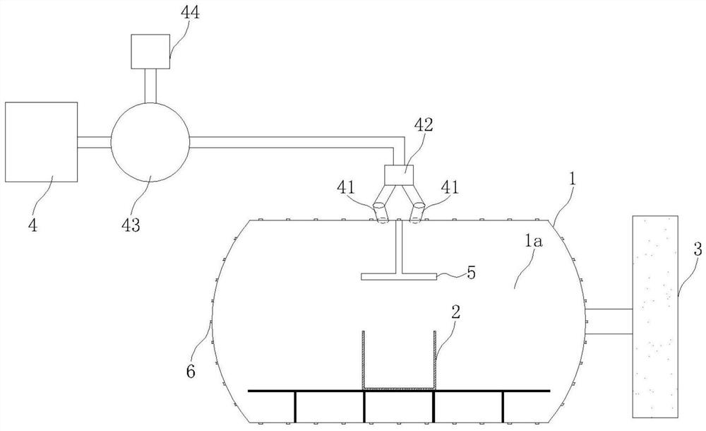
[0061] As an alternative to Embodiment 1, this embodiment is based on Embodiment 1, such as figure 2 As shown, the wave source 4 is connected to the circulator 43, the transmission port of the circulator 43 is connected to the rectangular waveguide 41, the reflection port of the circulator 43 is connected to the absorbing load 44, the rectangular waveguide 41 is connected to the 1-to-2 power splitter 42, and the two-way power splitter 42 The microwave ports are respectively connected through the rectangular waveguide 41 converters, which is more conducive to uniform heating.

Embodiment 3

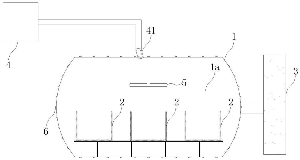
[0063] As an alternative to Embodiment 1, this embodiment is based on Embodiment 1, such as image 3 As shown, three crucibles 2 are arranged on the heat shield 21, and an insulation layer 22 is arranged outside each crucible 2, so as to realize simultaneous heating of multiple stations and improve melting efficiency.

[0064] As an optional mode of the above-mentioned embodiment, in other embodiments, the microwave mouth is facing the stirring paddle 5, which is beneficial to the stirring paddle 5 to make the electromagnetic field in the cavity 1a uniform; The gap angle cannot be 180°C to prevent microwave reflection, and the phases of each road are consistent.

[0065] As an optional mode of the above-mentioned embodiment, in other embodiments, the stirring paddle 5 is a metal stirring paddle 5, and the rotation diameter of the stirring paddle 5 is not less than 1 / 4 of the microwave wavelength, and more preferably the rotation diameter of the stirring paddle 5 is the microwa...


PUM

PropertyMeasurementUnit
diameteraaaaaaaaaa
lengthaaaaaaaaaa
diameteraaaaaaaaaa

Abstract

The invention discloses a vacuum microwave smelting device. The vacuum microwave smelting device comprises a furnace body, a crucible, a vacuum system, a wave source, a stirring paddle and a cooling pipeline, wherein the furnace body is a horizontal furnace body with a containing cavity, and a microwave breach is formed in the furnace body; the crucible is arranged in the containing cavity, does not make direct contact with the furnace body and is used for metal smelting; the vacuum system communicates with the containing cavity and is used for vacuumizing the containing cavity; the wave source is connected with the microwave breach through a waveguide and is used for conveying microwaves to the containing cavity; the stirring paddle is arranged in the containing cavity and is used for changing electromagnetic field distribution in the containing cavity; and the cooling pipeline is arranged on the furnace body. According to the vacuum microwave smelting device, the single microwave source, large working area, high vacuum and uniform electromagnetic field space distribution statistics are realized, thus uniform heating is guaranteed, and local overheating is avoided.

Description

technical field [0001] The invention relates to a vacuum microwave smelting device, which belongs to the technical field of microwave metal smelting. Background technique [0002] Traditional metal smelting methods, such as arc smelting, induction smelting, etc., consume a lot of energy during the operation of the equipment, waste of materials and energy will occur during the smelting process, and there are safety risks. In order to overcome the shortcomings of traditional smelting, some advanced smelting technologies, such as electron beam smelting, infrared smelting, plasma smelting, microwave smelting, etc. The advantages of small environmental hazards have aroused widespread concern. As a clean and environmentally friendly heating method, microwave technology has potential engineering application value in the field of metal smelting. At present, the design of the furnace body of the microwave industrial application equipment used is mostly based on the resonant cavity ...

Claims


Application Information

Patent Timeline
Patent Type & Authority Applications(China)
IPC IPC(8): F27B14/04F27B14/06F27B14/14F27B14/10F27D1/18F27D27/00
CPCF27B14/04F27B14/06F27B14/14F27B14/10F27D1/1858F27D27/00F27B2014/045F27M2003/13
Inventor 闫二艳何琥刘泾源郑强林陈世韬苏斌鲍向阳杨浩聂勇陈志国黄诺慈
Owner INST OF APPLIED ELECTRONICS CHINA ACAD OF ENG PHYSICS
Why Eureka
Try Eureka