
Annular laser cladding nozzle

A laser cladding and nozzle technology, which is applied in the coating process and coating of metal materials, can solve the problems of complex operation, complex processing procedures, uneven powder feeding, etc.

Pending Publication Date: 2021-10-08
宁波海天激光科技有限公司
View PDF0 Cites 0 Cited by
  • Summary
  • Abstract
  • Description
  • Claims
  • Application Information

AI Technical Summary

Problems solved by technology

However, at present, laser cladding nozzles often have defects such as complicated processing procedures, complicated operations, and uneven powder feeding.

Method used


Image

  • Annular laser cladding nozzle
  • Annular laser cladding nozzle
  • Annular laser cladding nozzle

Examples


Embodiment Construction

[0030] Embodiments of the present invention will be further described in detail below in conjunction with the accompanying drawings.

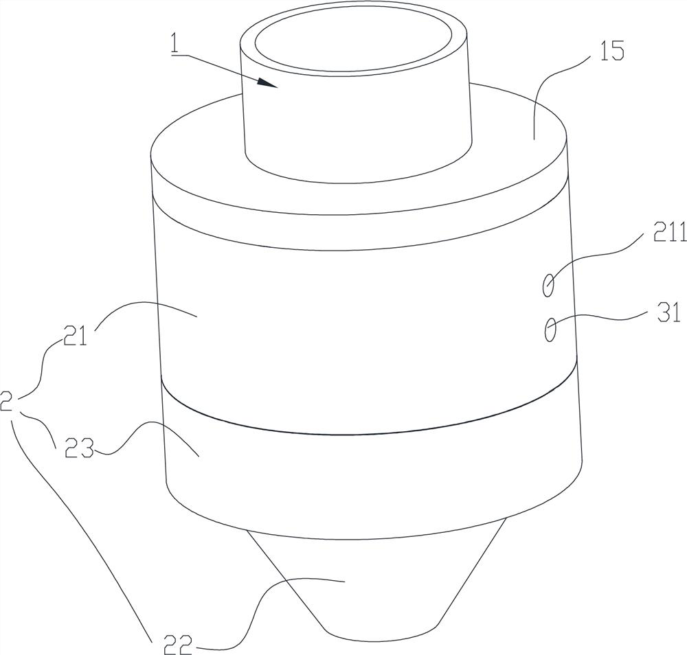
[0031] Figure 1 to Figure 7 It is a structural schematic diagram of the present invention.

[0032] The reference signs therein are: inner core 1, outer jacket 2, laser channel 11, opening 111, mixing chamber 3, second conveying channel 4, first conveying channel 31, groove 12, slope surface 14, circular arc depression 13 , coolant flow channel 212, liquid injection port 211, liquid discharge port 213, ring protrusion 15, processing groove 214, first seal 5, channel part 21, cone head part 22, concave-convex matching structure 61, second seal Part 62, the outer ring fixing sleeve 23, the first stepped surface 221, and the second stepped surface 231.

[0033] Figure 1 to Figure 7 It is a schematic diagram of the structure of the present invention. The "tail end" referred to in this embodiment refers to the end in the same direction as the l...


PUM


Abstract

The invention discloses an annular laser cladding nozzle comprising an inner core and an outer sleeve arranged outside the inner core in a sleeving mode, a laser channel is formed in the center of the inner core, and an opening allowing laser to be emitted out is formed in the center of the inner core; a material mixing chamber is arranged between the inner core and the outer sleeve, and a second conveying channel for outputting metal powder is arranged between the material mixing chamber and the opening; the material mixing chamber is communicated with more than one first conveying channel for inputting the metal powder; and the inner core is also provided with grooves facing the material mixing chamber. Preferably, the number of the first conveying channels is two. The multiple grooves are formed in the surface of the inner core at equal intervals, when powder and gas are mixed and enter the material mixing chamber, due to the existence of the grooves, the powder continuously impacts the grooves and forms cyclone, the powder continuously impacts back and forth in the material mixing chamber, and therefore uniform powder feeding is achieved. In order to improve the powder mixing and feeding effect, the preferable scheme of the material mixing chamber and the second conveying channel is that the material mixing chamber and the second conveying channel are of a rotary structure with the central axis of the laser channel as the center. The grooves are arranged in the inner core in an annular array.

Description

technical field [0001] The invention belongs to the field of laser cladding, and in particular relates to an annular laser cladding nozzle. Background technique [0002] Laser cladding technology is a new surface modification technology. The processing process is to add external materials to the molten pool formed after the substrate is irradiated by laser through synchronous or preset materials, and make the two solidify rapidly together. Process method for forming cladding layer. [0003] In the application of laser processing technology, the laser nozzle is one of the most critical equipment. The uniformity of the powder injected from the nozzle largely determines the processing quality of the equipment. However, at present, laser cladding nozzles often have defects such as complicated processing procedures, complicated operations, and uneven powder feeding. Contents of the invention [0004] The technical problem to be solved by the present invention is to provide an...

Claims


Application Information

Patent Timeline
Patent Type & Authority Applications(China)
IPC IPC(8): C23C24/10B22F1/00
CPCC23C24/103
Inventor 毛杰王凯
Owner 宁波海天激光科技有限公司
Learn More