
Aerial operation robot carrying double longitudinal active telescopic mechanical arms

A technology for working robots and mechanical arms, which is applied to manipulators, unmanned aerial vehicles, claw arms, etc., can solve the problems of changing working conditions, low working efficiency, poor safety, etc. Effect

Pending Publication Date: 2021-10-08
GUIZHOU POWER GRID CO LTD
View PDF5 Cites 0 Cited by
  • Summary
  • Abstract
  • Description
  • Claims
  • Application Information

AI Technical Summary

Problems solved by technology

The current cleaning of floating objects on cables is mainly done manually, which has poor safety, low operating efficiency, and certain limitations; while the method of removing floating objects using drones carrying mechanical arm operating devices has many advantages, but traditional machinery The way the arm is fixed to the UAV makes the operation state of the specific attitude of the manipulator change with the pitch angle of the UAV

Method used


Image

  • Aerial operation robot carrying double longitudinal active telescopic mechanical arms
  • Aerial operation robot carrying double longitudinal active telescopic mechanical arms
  • Aerial operation robot carrying double longitudinal active telescopic mechanical arms

Examples


Embodiment 1

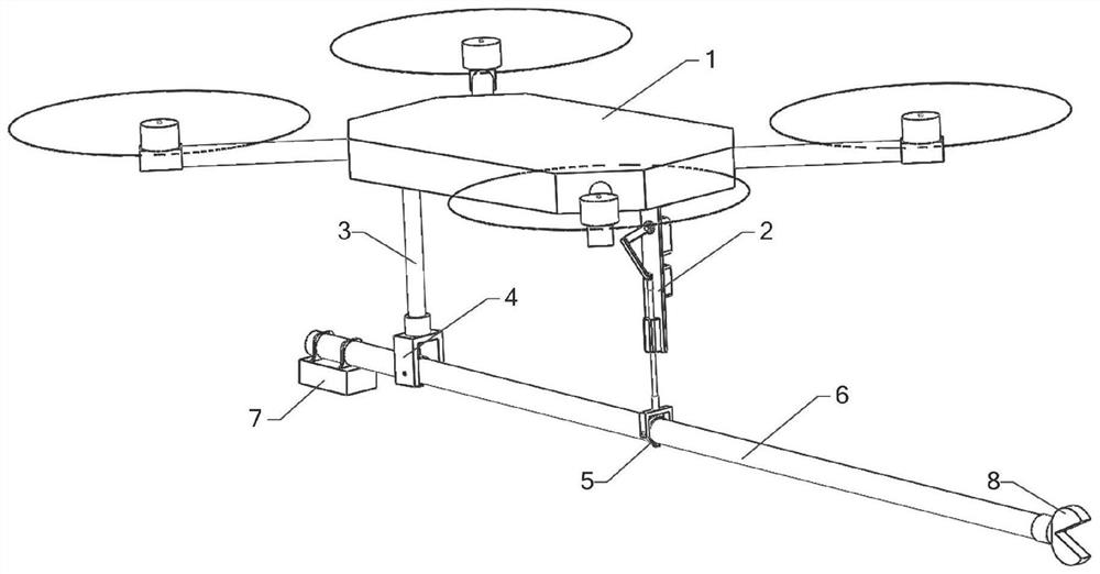
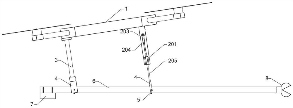
[0033] Embodiment 1: as Figure 1 to Figure 5 As shown, an aerial work robot equipped with a self-balancing mechanical arm includes a flying platform 1, a self-balancing telescopic system 2 fixedly connected to the bottom of the flying platform 1, a fixed rod 3 connected to the bottom of the flying platform 1, and a fixed rod connected to the fixed rod. 3 the rotating bracket 4 at the end, the mechanical arm 6 connected to the rotating bracket 4 through the pipe clamp 5, the operating system 8 connected to the front end of the mechanical arm 6, the power supply system 7 connected to the end of the mechanical arm for the mechanical arm 6 and the operating system 8 to work, There is a rotating shaft at both ends of the pipe clamp 5, which can rotate around the rotating bracket.

[0034] Preferably, the above-mentioned self-balancing manipulator system 2 includes a mounting plate 201 connected to the bottom of the flight platform 1, a steering gear 202 fixed on the mounting plate...

Embodiment 2

[0040] Embodiment 2: as Figure 2 to Figure 5 As shown, the control method of the self-balancing telescopic system of the flying platform 1 under different attitudes is as follows:

[0041] When the attitude of the aerial robot is horizontal, the steering gear arm 203 and the mechanical arm 6 are also in a horizontal state, as figure 2 As shown, the self-balancing controller obtains the pitch angle data of the flying platform in real time through Bluetooth, and controls the steering gear 202 to rotate the steering gear arm 203 to drive the reciprocating rod 205 to reciprocate through the PID control algorithm, so that it automatically follows the pitch angle change of the flying platform, thereby Keep the mechanical arm 6 in a horizontal state.

[0042] When the pitch angle of the aerial robot is greater than 0, the pitch angle is Y 1 , deviation E 1 =Y 1 -0; when the pitch angle is greater than 0, the pitch angle is Y 2 , deviation E 2 =0-Y 2 , the time for the attitud...


PUM


Abstract

The invention discloses an aerial operation robot carrying a self-balancing mechanical arm. The aerial operation robotincludes a flying platform, a self-balancing telescopic system fixedly connected to the lower portion of the flying platform, a mechanical arm connected with the self-balancing telescopic system, a fixing rod fixedly connected to the lower portion of the flying platform and connected with the mechanical arm, an operation system connected to the front end of the mechanical arm, and a power supply system connected to the tail end of the mechanical arm and used for supplying power to the mechanical arm and the operation system for working. The self-balancing telescopic system can automatically stretch out and draw back according to the attitude angle of the flying platform to keep the horizontal or specific operation state of the mechanical arm, the structure is simple, control is convenient, remote operation is achieved, the operation safety is high, and the floating object cleaning efficiency is high; the problem that in the prior art, a mechanical arm cannot maintain horizontal or specific attitude stable operation along with the attitude angle change of a flying platform is solved.

Description

technical field [0001] The invention relates to an aerial work robot equipped with dual longitudinal active telescopic arms, and belongs to the technical field of floating object cleaning devices for overhead cables. Background technique [0002] In recent years, incidents of damage to transmission line channels caused by high-altitude floating objects entangled on overhead lines have occurred frequently, such as short-circuiting between lines, increase in line burden, etc. The impact of high-altitude floating objects on transmission lines seriously threatens the operation safety of transmission lines, and is a hidden danger in the current transmission line channels. To this end, power departments at all levels have to invest a lot of manpower, material and financial resources every year to clean up and renovate overhead cables in their jurisdictions. The current cleaning of floating objects on cables is mainly done manually, which has poor safety, low operating efficiency,...

Claims


Application Information

Patent Timeline
Patent Type & Authority Applications(China)
IPC IPC(8): B64C39/02B64C17/00B25J18/02H02G1/02
CPCB64C39/024B64C17/00B25J18/025H02G1/02B64U10/10
Inventor 张秋雁杨忠陶坤陈科宇许昌亮吴吉莹王炜梁家斌张海永
Owner GUIZHOU POWER GRID CO LTD
Learn More