Carton production stable grooving equipment facilitating scrap cleaning
A grooving equipment and chip technology, which is applied in the manufacture of papermaking, paper/cardboard containers, rigid/semi-rigid containers, etc. Different groove positions, improve work efficiency, and facilitate the effect of collecting debris
- Summary
- Abstract
- Description
- Claims
- Application Information
AI Technical Summary
Problems solved by technology
Method used
Image
Examples
Embodiment 1
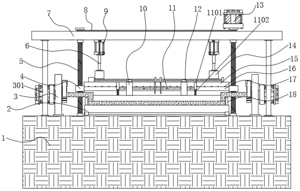
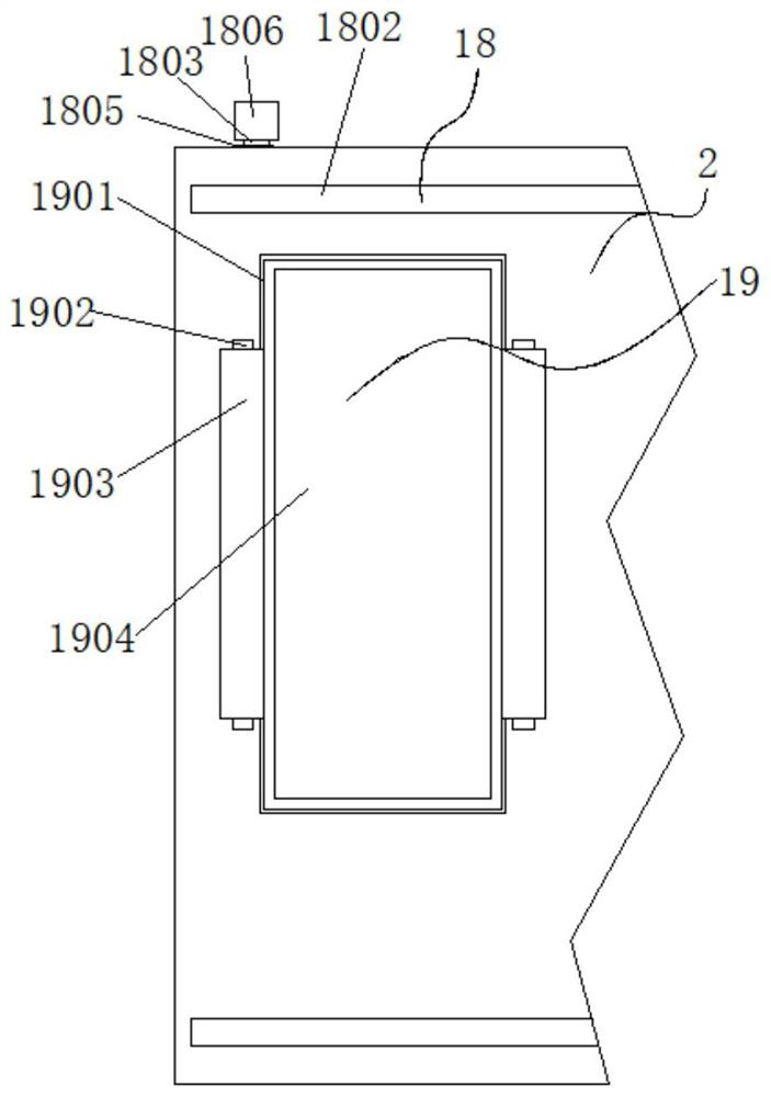
[0039] Example 1: See Figure 1-6 , a stable slotting device for carton production that is convenient for cleaning debris, comprising a worktable 1 and a processing table 2, the top of the workbench 1 is fixedly connected with a top plate 7 through a connector, and the top of the workbench 1 is fixedly connected with a processing table 2, The top of the processing table 2 is provided with an auxiliary finishing structure 18, and the interior of both sides of the top of the processing table 2 is provided with an auxiliary collection structure 19. Auxiliary cleaning structure 11 is arranged, and the bottom end of top plate 7 is fixedly connected with hydraulic cylinder 9, and the model of this hydraulic cylinder 9 can be J64RT2UNIVER, and the bottom end of hydraulic cylinder 9 is fixedly connected with telescopic rod 6, and the bottom end of telescopic rod 6 is provided with opening The slotter 14, the bottom end of the slotter 14 is provided with an auxiliary adjustment and fix...
Embodiment 2
[0043] Embodiment 2: the auxiliary pushing mechanism 3 is made up of the first drive motor 301, support plate 302, movable shaft 303, rack 304, gear 305, limit groove 306, push plate 307 and limit block 308, the support plate 302 The bottom end is fixedly connected to the top of the workbench 1. One side of the support plate 302 is provided with a first drive motor 301. The model of the first drive motor 301 can be Y90S-2, and the other side of the support plate 302 is fixedly connected to a limit Slot 306, the output end of the first drive motor 301 runs through the inside of one side of the support plate 302 through the drive shaft and is fixedly connected with the gear 305 through the connector. There is a rack 304 fixedly connected to the outside of the center, one end of the movable shaft 303 is fixedly connected to the limit block 308, and a push plate 307 is fixedly connected between one side of the movable shaft 303;
[0044] The rack 304 is meshed with the gear 305, a...
Embodiment 3
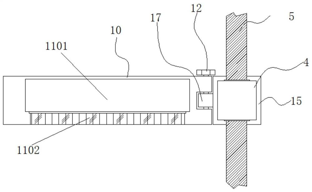
[0046] Embodiment 3: as figure 1 and Figure 4 , 7 , 8, the auxiliary cleaning structure 11 is made up of a mounting block 1101, a brush bar 1102, a movable rod 1103, a through groove 1104 and a handle 1105, the through groove 1104 is arranged inside the movable platen 10, and the through groove 1104 is arranged transversely There is a movable rod 1103, one side of the movable rod 1103 is fixedly connected with a handle 1105, the other side of the movable rod 1103 is fixedly connected with a mounting block 1101, and the bottom end of the mounting block 1101 is fixedly connected with a brush bar 1102;
[0047] The movable rod 1103 is embedded in the inside of the through groove 1104, and the bottom end of the brush strip 1102 and the bottom end of the movable platen 10 are at the same level;
[0048] The surface of the fixed block 15 is horizontally provided with a guide groove 23, the left end of the guide groove 23 is provided with a bearing seat 25, the right end of the gu...
PUM
 Abstract
Description
Claims
Application Information
 - R&D
- Intellectual Property
- Life Sciences
- Materials
- Tech Scout
- Unparalleled Data Quality
- Higher Quality Content
- 60% Fewer Hallucinations
Browse by: Latest US Patents, China's latest patents, Technical Efficacy Thesaurus, Application Domain, Technology Topic, Popular Technical Reports.
© 2025 PatSnap. All rights reserved.Legal|Privacy policy|Modern Slavery Act Transparency Statement|Sitemap|About US| Contact US: help@patsnap.com


