3D printer

A 3D printer and driving motor technology, applied in the field of 3D printing, can solve the problems of poor structure of the finished product, inability to print, slippage of the feeding device, etc., and achieve the effect of fast heating efficiency, improved printing effect, and molding standard.

Active Publication Date: 2021-10-08
深圳市俩棵树科技有限公司
View PDF12 Cites 0 Cited by
  • Summary
  • Abstract
  • Description
  • Claims
  • Application Information

AI Technical Summary

Problems solved by technology

This invention realizes anti-drawing by pulling back the material wire, but it takes time to pull back the process in actual use, so it will still cause partially melted material wire to flow out along the nozzle to cause wire drawing, the wire drawing effect is poor, and the wire drawing efficiency is low
[0004] At the same time, if the filament is defective or knotted during actual use, the feeding device of the 3D printing will slip or be blocked, resulting in the inability to print and reducing the printing efficiency. At the same time, the position of the nozzle of the 3D printer will be blocked when used for a long time Phenomenon, resulting in deterioration of the structure of the finished product

Method used


Image

  • 3D printer
  • 3D printer
  • 3D printer

Examples


no. 1 example

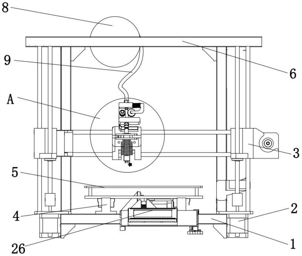
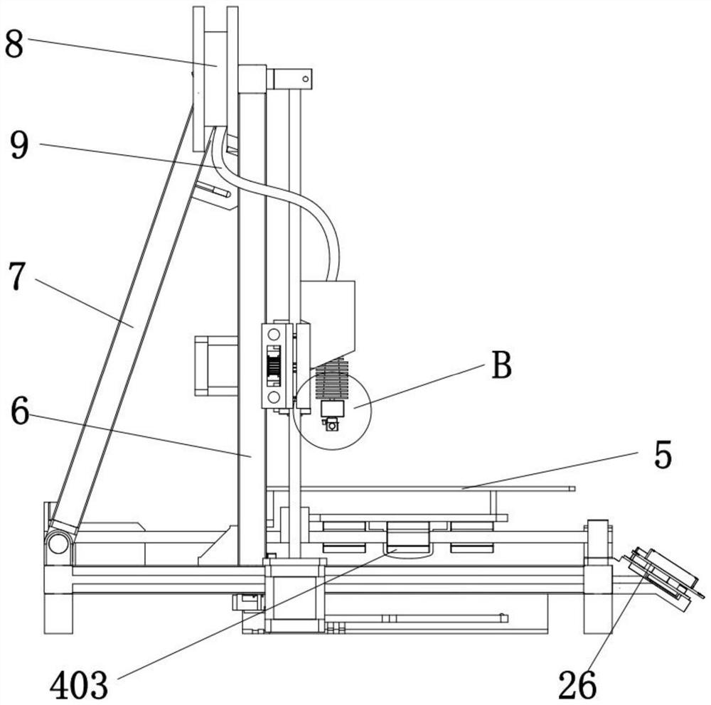
[0024] First Example: Combining Figure 1-3 , the present embodiment provides a 3D printer, comprising a base plate 1, a controller 26 is provided on one side of the base plate 1, and the controller 26 electrically controls each electrical component, a bracket 6 is provided on the top of the base plate 1, and the connection between the base plate 1 and the bracket 6 Reinforcing ribs 7 are provided between them, and the reinforcing ribs 7 are used to strengthen the strength of the whole device and prevent the bracket 6 from being bent and damaged. The opposite sides of the bottom plate 1 are provided with a Z-direction power device 2, and the outer surface of the Z-direction power device 2 is slidingly connected. There is an X-direction power device 3, the outer surface of the X-direction power device 3 is slidingly connected with a feeding device 10, the top of the bottom plate 1 is provided with a Y-direction power device 4, and the outer surface of the Y-direction power devic...

no. 2 example

[0032] Based on the first embodiment, there will be defects or knots in the material filament 9 during actual printing. When the material filament 9 is defective, the feeding device 10 will slip and cannot feed further. Similarly, when the material filament 9 is knotted, the feeding device 10 will 10, there will be a blockage, and it is also impossible to feed further; and there will be a printing gap during printing. This position requires that the nozzle 12 does not discharge. If only the feeding device 10 does not feed or return the material, there will still be part of the melted material. The filament 9 flows out from the nozzle 12 to cause wire drawing. Excessive wire drawing will affect the printing quality, reduce the printing effect, and increase the difficulty of repeated corrections. In addition, the nozzle 12 will inevitably be blocked during the printing process for a long time, resulting in insufficient output from the nozzle 12. Uniformity, reduce the printing ef...


PUM


Abstract

The invention belongs to the technical field of 3D printing, and discloses a 3D printer. The 3D printer comprises a bottom plate, wherein a controller is arranged at one side of the bottom plate, a support is arranged at the top of the bottom plate, a Z-direction power device is arranged at one side of the bottom plate, and an X-direction power device is slidably connected to the outer surface of the Z-direction power device; and the X-direction power device is arranged at the top of the bottom plate, a feeding device is slidably connected to the outer surface of the X-direction power device, a Y-direction power device is arranged at the top of the bottom plate, a hot plate is arranged on the outer surface of the Y-direction power device, a heating pipe is communicated with the bottom of the feeding device, and a spray head is arranged at the bottom of the heating pipe. According to the 3D printer, movement of a material wire is detected through a displacement sensor, a blocking lead screw is controlled to block a discharging port, and meanwhile, the discharging time is controlled through the pressure value detected by a pressure sensor, the problems of feeding slipping or blocking caused by printing wire drawing, material wire defects or knotting are solved, the problem that the spray head is blocked can be solved, the printing efficiency is improved and the printing effect is ensured.

Description

technical field [0001] The invention belongs to the technical field of 3D printing, in particular to a 3D printer. Background technique [0002] 3D printer, a machine of rapid prototyping technology, is a technology based on digital model files and using bondable materials such as powdered metal or plastic to construct objects by layer-by-layer printing. In the past, it was often used to make models in the fields of mold manufacturing and industrial design, and is now gradually being used in the direct manufacturing of some products, which means that this technology is becoming popular. Its principle is: Put the data and raw materials into the 3D printer, and the machine will make the product layer by layer according to the program. The printed product can be used immediately. Food can also be printed with a 3D printer. This is also the future development direction of 3D printers that most foodies are concerned about. [0003] Chinese invention patent CN201711205398.2 di...

Claims


Application Information

Patent Timeline
Patent Type & Authority Applications(China)
IPC IPC(8): B29C64/118B29C64/232B29C64/236B29C64/393B29C64/321B33Y10/00B33Y30/00B33Y40/00B33Y50/02
CPCB29C64/118B29C64/232B29C64/236B29C64/393B29C64/321B33Y10/00B33Y30/00B33Y40/00B33Y50/02Y02P10/25
Inventor 白万涛
Owner 深圳市俩棵树科技有限公司
Why Eureka
Try Eureka