Filter pipe forming device

A molding device and filter tube technology, applied in ceramic molding machines, manufacturing tools, molds, etc., can solve the problems of reducing the vacuum inside the drum, aggravating equipment wear, and increasing the weight of rotating parts, so as to increase the drainage point and improve the quality , Improve the effect of uniformity

Pending Publication Date: 2021-10-08
汪家勤
View PDF6 Cites 1 Cited by
  • Summary
  • Abstract
  • Description
  • Claims
  • Application Information

AI Technical Summary

Problems solved by technology

[0005] Most of the existing molding devices place the mold in the drum, and the mold is rotated by rotating the drum. This method increases the weight of the rotating parts and aggravates the wear of the equipment; vacuum inside the drum

Method used


Image

  • Filter pipe forming device
  • Filter pipe forming device
  • Filter pipe forming device

Examples


Embodiment 1

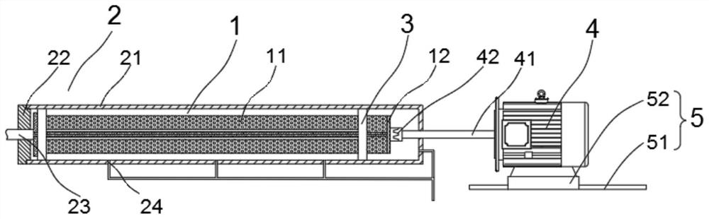
[0033] Specifically, as figure 1 As shown, the housing 1 is a cylindrical body 21 with one end closed, and a liquid discharge port 24 is provided at the closed end of the cylindrical body 21, and three liquid discharge ports 24 are provided at the bottom of the cylindrical body 21, and the three liquid discharge ports are evenly distributed in the cylinder. In the length direction of the body 21, the liquid discharge port 24 is connected to the negative pressure mechanism through a pipeline, and is used to suck the slurry out of the cylinder body, so that the cylinder body is in a vacuum state; one end of the cylinder body 21 opening is provided with a sealing cover 22, and A feed pipe 23 is provided, and the feed pipe 23 extends into the cylinder and extends into the molding die 1 .

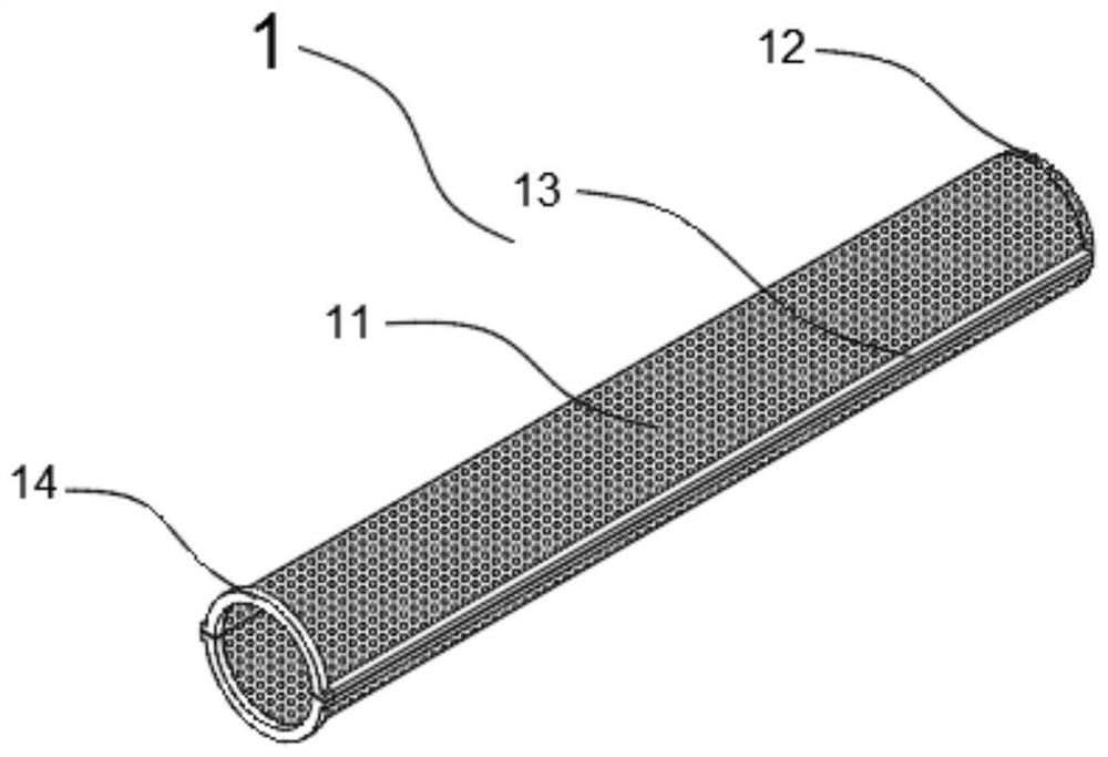
[0034] Such as figure 2 As shown, the molding die 1 includes a tubular body 11 and a bottom cover 12, the bottom cover 12 is provided with a coupling 42, the tubular body 11 is surrounded by t...

Embodiment 2

[0040] Such as Figure 4 A filter tube molding device shown includes a molding die 1, a casing 2, a rotating mechanism 3, a drive motor 4 and a negative pressure mechanism (not shown), the casing 2 is an openable airtight casing, and the casing 2 is provided with The feed pipe 23 and the liquid discharge port 24, the feed pipe 23 communicates with the forming mold 1, the liquid discharge port 24 is connected with the negative pressure mechanism; the rotating mechanism 3 is arranged in the shell 2, the forming mold 1 is connected with the rotating mechanism 3, and the driving motor The driving shaft 41 of 4 extends into the housing 2 and is connected with the rotating mechanism 3 for driving the forming mold 1 to rotate.

[0041] Specifically, as Figure 4 As shown, the housing 2 includes an upper half pipe 25 and a lower half pipe 26, the cross section of the upper half pipe 25 is smaller than the cross section of the lower half pipe 26, and the two ends of the upper half pip...


PUM


Abstract

The invention discloses a filter pipe forming device which comprises a forming mold, a shell, a rotating mechanism, a driving motor and a negative pressure mechanism, wherein the shell is a closed shell capable of being opened, a feeding pipe and a liquid discharging opening are formed in the shell, the feeding pipe is communicated with the forming mold, and the liquid discharging opening is connected with the negative pressure mechanism; the rotating mechanism is arranged in the shell, the forming die is connected with the rotating mechanism, and a driving shaft of the driving motor extends into the shell to be connected with the rotating mechanism or the forming die and used for driving the forming die to rotate. Through an internal rotating structure, the weight of a rotating part is reduced, the abrasion of equipment is reduced, and the service life of the equipment is prolonged; and meanwhile, control over centrifugal force is improved, so that the internal structure of the product is controllable, the product quality is improved, and meanwhile the product diversification is improved; by means of the fixed shell structure, the arrangement range of the liquid discharging port is widened, liquid discharging points are increased, the uniformity of negative pressure in the cavity is improved, and then the uniformity of the product structure is improved.

Description

technical field [0001] The invention relates to the technical field of ceramic fiber filter tube production equipment, in particular to a filter tube forming device. Background technique [0002] The preparation of ceramic fiber filter tubes mainly includes short fiber suction molding process, continuous fiber weaving and winding process. The continuous fiber weaving and winding process is subject to the influence of the type and price of continuous fiber, the manufacturing cost is relatively high, and there is a certain degree of large-scale promotion. However, the products prepared by short fiber suction filtration molding have the advantages of high porosity, low filtration resistance, simple preparation process, low preparation cost, and convenient large-scale production. It is currently the most common preparation process at home and abroad. The high-temperature ceramic fiber filter material prepared by the suction filtration molding process has been widely used in the ...

Claims


Application Information

Patent Timeline
Patent Type & Authority Applications(China)
IPC IPC(8): B28B21/32B28B21/40B28B21/80B28B21/82
CPCB28B21/32B28B21/40B28B21/80B28B21/82
Inventor 汪家勤
Owner 汪家勤
Why Eureka
Try Eureka