
Fixtures for the crank arm

A tooling fixture and fixture technology, applied in the direction of manufacturing tools, clamping, positioning devices, etc., can solve the problems affecting the beautiful appearance of the crank arm, the high cost of processing methods, and the long labor hours, so as to shorten the processing time, beautiful appearance, Reduce the effect of machining processes

Active Publication Date: 2022-04-12
BEIJING SOJO ELECTRIC
View PDF7 Cites 0 Cited by
  • Summary
  • Abstract
  • Description
  • Claims
  • Application Information

AI Technical Summary

Problems solved by technology

The above-mentioned processing methods are costly, complicated, and time-consuming, and the weld scars left by the welding process affect the appearance of the crank arm

Method used


Image

  • Fixtures for the crank arm
  • Fixtures for the crank arm
  • Fixtures for the crank arm

Examples


Embodiment Construction

[0020] In order to make the above objects, features and advantages of the present invention more comprehensible, specific embodiments of the present invention will be described in detail below in conjunction with the accompanying drawings.

[0021] The directions or positional relationships indicated by the terms "upper", "lower", "front", "rear", "left" and "right" appearing in the embodiments of the present invention are based on the orientation or positional relationships shown in the drawings , is only for the convenience of describing the present invention and simplifying the description, but does not indicate or imply that the referred device must have a specific orientation, be constructed and operated in a specific orientation, and thus should not be construed as limiting the present invention.

[0022] In the description of the present invention, it should be noted that, unless otherwise clearly specified and limited, the terms "setting", "installation", "connection" a...


PUM


Abstract

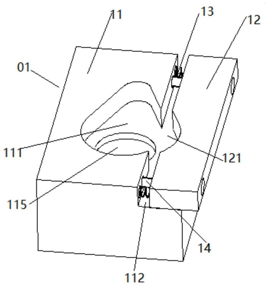
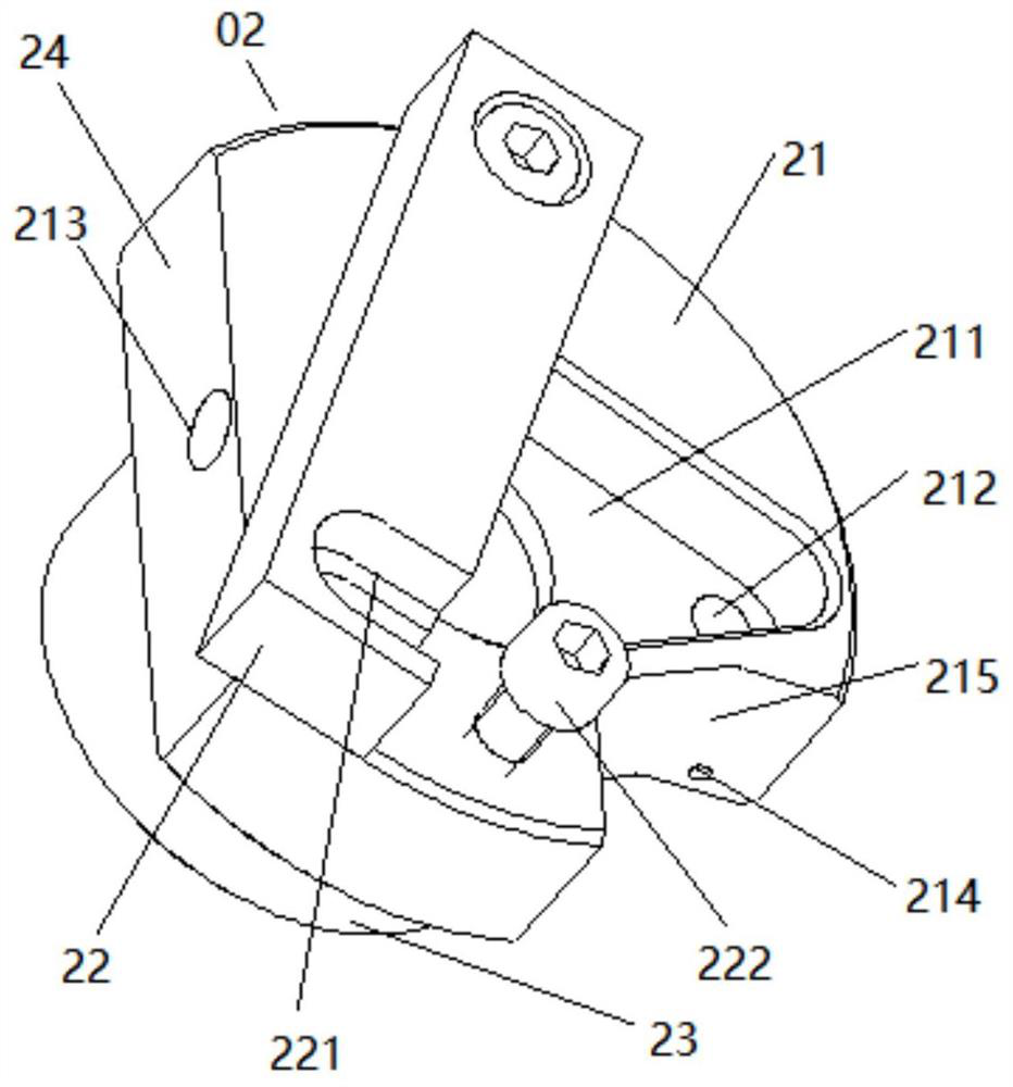
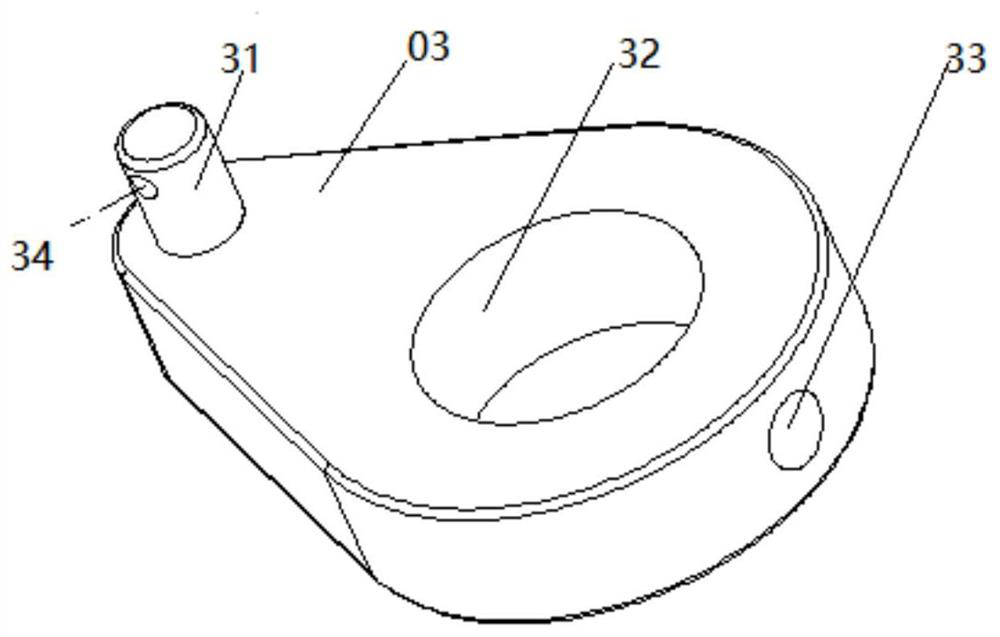
The invention provides a tooling clamp for a crank arm, which belongs to the technical field of mechanical equipment, and specifically includes a first clamp assembly and a second clamp assembly, the first clamp assembly includes a first base, a first pressure plate, and the first base The upper surface of the upper surface is provided with a first groove, and the upper surface of the first pressure plate is provided with a second groove. The size is suitable, the second fixture includes a second base, a second pressure plate and a clamping part, a third groove is opened on the second base, a counterbore is opened at the bottom of the third groove, and a counterbore is opened on the second base. The two pressing plates are used to position the crank arm, and the second base is also provided with a first processing hole and a second processing hole. The crank arm is processed by the jig of the crank arm of the present invention, which has the advantages of simple process, less working procedure and high efficiency, and the appearance of the crank arm is more beautiful.

Description

technical field [0001] The invention relates to a processing tool, in particular to a tooling fixture for a crank arm. Background technique [0002] The crank arm is an interlocking drive on the switchgear, and it is used in large quantities. The existing processing method is as follows: the shape of the crank arm and the big hole of the crank arm are made by the casting mold, and the large hole of the crank arm is reserved for processing, and the large hole of the crank arm is processed by a CNC lathe, and then the hole is positioned to make the front end of the drilling mold. The positioning hole of the pin, and then the processed pin is welded to the crank arm by means of hole positioning. The above-mentioned processing method has high cost, complex process and long working hours, and the welding scars left in the welding process affect the appearance of the crank arm. Contents of the invention [0003] The problem to be solved by the present invention is to provide a...

Claims


Application Information

Patent Timeline
Patent Type & Authority Patents(China)
IPC IPC(8): B23Q3/06
CPCB23Q3/062
Inventor 林忠波李浩符卓聪贾艳飞
Owner BEIJING SOJO ELECTRIC
Learn More