Aerial pipeline arranging structure for horizontal numerical control rotary table

A CNC turntable and pipeline technology, which is used in metal processing equipment, metal processing mechanical parts, large fixed members, etc., can solve the problems of pipeline winding, many pipelines, twisting, etc., to achieve the overall compact optimization, the machine tool runs fast, and the The effect of pipe routing simplification

Active Publication Date: 2021-10-08
NINGBO HAITIAN PRECISION MASCH CO LTD
View PDF9 Cites 0 Cited by
  • Summary
  • Abstract
  • Description
  • Claims
  • Application Information

AI Technical Summary

Problems solved by technology

The structure of the pipeline inside the workbench is complex, and there are many pipelines, which will occupy the inner space of the workbench, resulting in an increase in the thickness of the workbench, which will affect the performance and structural parameters of the whole machine
The pipe swinging outside the workbench is usually only suitable for the workbench that moves in a straight line or rotates at a small angle, but it is not feasible for the workbench that rotates 360 degrees, which will cause the pipeline to be entangled and twisted, and affect the service life of the pipeline

Method used


Image

  • Aerial pipeline arranging structure for horizontal numerical control rotary table
  • Aerial pipeline arranging structure for horizontal numerical control rotary table
  • Aerial pipeline arranging structure for horizontal numerical control rotary table

Examples


Embodiment Construction

[0024] The present invention will be further described in detail below in conjunction with the accompanying drawings and embodiments.

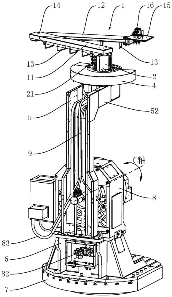
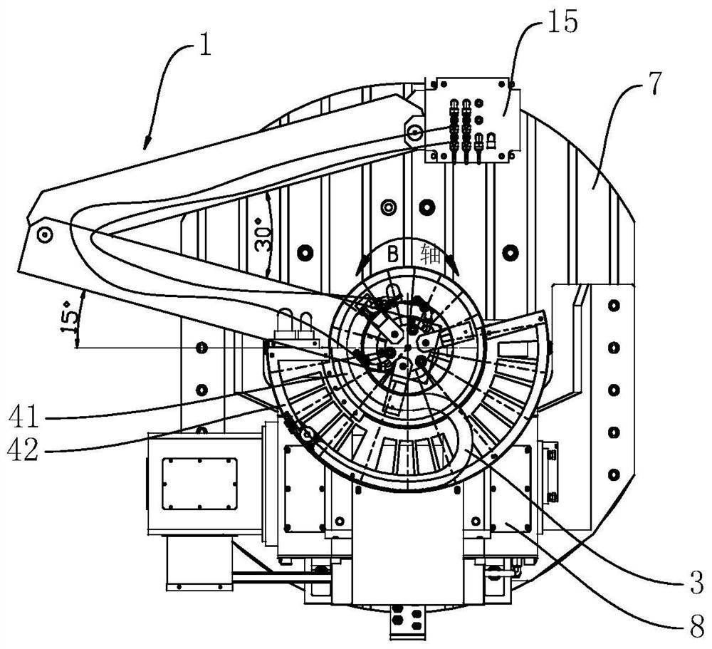
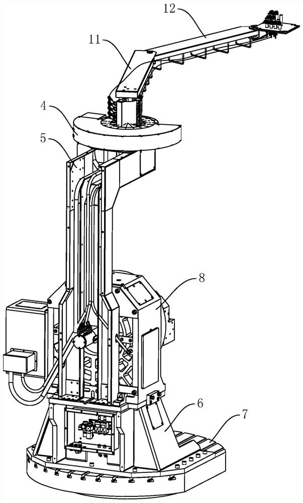
[0025] The aerial pipeline structure of the lying plus CNC turntable of the embodiment, such as Figure 1 to Figure 6 As shown, it includes connecting rod 1, rotating distributor 2, rotating towline 3, rotating towline trough 4, wiring trough support 5 and base 6, connecting rod 1 is a foldable connecting rod 1, and the lower side of connecting rod 1 A number of lifting lugs 13 are fixed for pipelines to pass through and hang. The rotating drag chain 3 is coaxially arranged directly above the workbench 7. The rotating drag chain 3 is bent and arranged in the rotating drag chain groove 4. The ends are respectively fixed in the rotary towline tank 4, and the rotation range of the rotary towline 3 is ±180°. In this embodiment, the rotary distributor 2 adopts the prior art, and the rotary distributor 2 is provided with several first pipe joints 21...


PUM


Abstract

The invention discloses an aerial pipeline arranging structure for a horizontal numerical control rotary table. The aerial pipeline arranging structure comprises a connecting rod, a rotary distributor, a rotary drag chain, a rotary drag chain groove, an arranging groove support and a base, wherein a plurality of lifting lugs are fixed on the lower side of the connecting rod, the rotary drag chain is coaxially arranged right above a workbench, the rotary drag chain with the rotation range of + / -180 degrees is arranged in the rotary drag chain groove in a bent mode, a plurality of first pipe joints are arranged on the rotary distributor, the upper end of the rotary distributor is hinged to the connecting rod, the lower end of the rotary distributor is fixed to the rotary drag chain groove, the rotary drag chain groove is fixed to the upper end of the arranging groove support, the lower end of the arranging groove support is fixed to the base, an arranging groove is formed in the back surface of the arranging groove support, the numerical control rotary table is fixed to the base, the arranging groove support is fixed to the numerical control rotary table, and the base is fixed to the workbench. According to the aerial pipeline arranging structure, connection of an externally-hung cable, an oil pipe and an air pipe on the 360-degree rotary workbench is achieved, so that a horizontal machining center machine tool conducts pipeline arranging in a semi-open mode within a machining area range, and chip stacking and chip hanging are not prone to occur.

Description

technical field [0001] The invention relates to a pipeline running structure applied to a numerical control machine tool, in particular to a pipeline running structure in the air with a horizontally mounted numerical control turntable. Background technique [0002] The existing commonly used horizontal processing CNC turntable usually adopts two types of pipeline routing, one is to route the pipeline from the inside of the horizontal processing table, and the other is to route the pipeline from the outside of the horizontal processing table, that is, in the horizontal processing table Hang the sling on the protection, hang all the pipelines, and make the pipelines rotate with the workbench. [0003] There are certain problems in the existing pipeline form of the horizontal plus numerical control turntable. The structural form of the pipeline inside the workbench is complex, and there are many pipelines, which will occupy the inner space of the workbench, resulting in an inc...

Claims


Application Information

Patent Timeline
IPC IPC(8): B23Q1/00B23Q1/72B23Q11/00
CPCB23Q1/00B23Q1/72B23Q11/00
Inventor 董田江严伟居中吴锋周鑫
Owner NINGBO HAITIAN PRECISION MASCH CO LTD
Why Eureka
Try Eureka