Drying chamber capable of replacing air valve by adjusting inserting plate

A technology of drying room and insert plate, applied in the field of drying room, can solve the problems of environmental pollution, leakage at the rotating shaft of the air valve, leakage of the air valve, etc., and achieve the effects of avoiding air pollution, uniform gas flow, and ensuring drying efficiency.

Pending Publication Date: 2021-10-01
DESIGN INST NO 9 MINISTRY OF MECHINE BUILDING
View PDF10 Cites 0 Cited by
  • Summary
  • Abstract
  • Description
  • Claims
  • Application Information

AI Technical Summary

Problems solved by technology

[0003] In the prior art, the end of the air supply pipe is usually divided into two pipes to dry the car body symmetrically. In order to ensure the same flow at both ends, the gas flow is adjusted by installing air valves at the ends of the two pipes. However, this Due to the leakage of the air valve shaft, the drying gas will escape to the external space, and the drying gas is basically a harmful gas, which will cause environmental pollution, and the external air pipe will turn yellow due to the leakage of the air valve. oil, which makes the surface quality of the equipment poor, so the present invention designs a drying chamber that replaces the air valve by adjusting the insert plate to solve the above problems

Method used


Image

  • Drying chamber capable of replacing air valve by adjusting inserting plate
  • Drying chamber capable of replacing air valve by adjusting inserting plate
  • Drying chamber capable of replacing air valve by adjusting inserting plate

Examples


Embodiment Construction

[0020] The following will clearly and completely describe the technical solutions in the embodiments of the present invention with reference to the accompanying drawings in the embodiments of the present invention. Obviously, the described embodiments are only some, not all, embodiments of the present invention. Based on the embodiments of the present invention, all other embodiments obtained by persons of ordinary skill in the art without making creative efforts belong to the protection scope of the present invention.

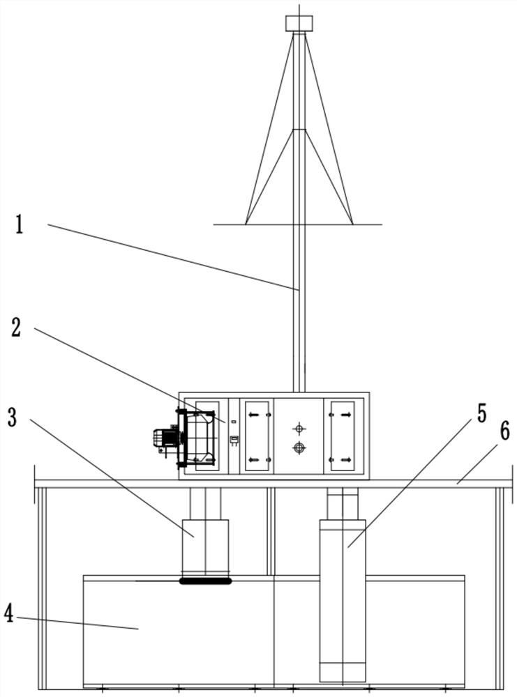
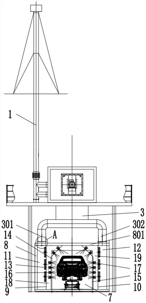
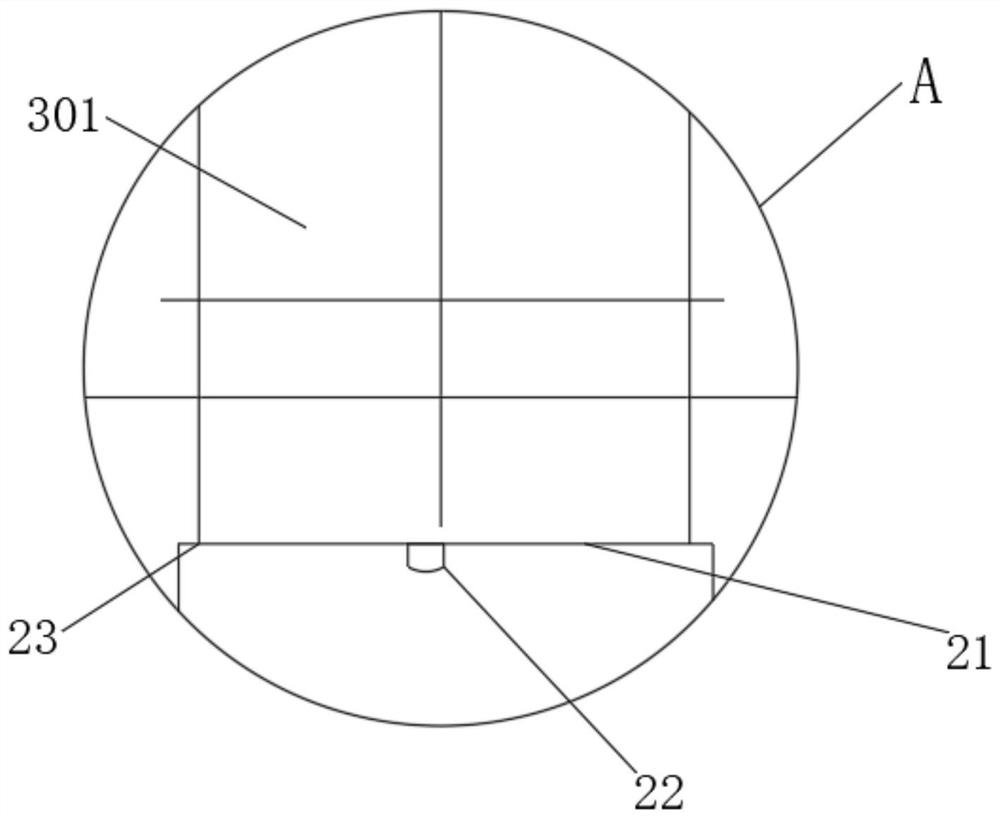
[0021] see Figure 1-4 , in an embodiment of the present invention, a drying chamber that replaces the air valve by adjusting the inserting plate, includes a heating heating unit 2, a steel platform 6, an inner cavity wall 8 and a drying work area 4, and the heating heating unit 2 Installed at the center of the top of the steel platform 6, the two ends of the bottom of the heating unit 2 are respectively connected with the air supply pipe 3 and the exhaust pip...


PUM


Abstract

The invention discloses a drying chamber capable of replacing an air valve by adjusting an inserting plate, and relates to the technical field of drying. The drying chamber comprises a temperature rising and heat supply unit, a steel platform, an air pipeline and a drying working area, the temperature rising and heat supply unit is installed on the steel platform, and the two ends of the bottom of the temperature rising and heat supply unit are connected with an air supply pipe and an exhaust pipe correspondingly. Stand columns are evenly and fixedly installed at the bottom of the steel platform, the bottom of the air supply pipe is divided into a left air pipe and a right air pipe, and the bottom of the left air pipe and the bottom of the right air pipe communicate with a top sealing plate at the top of an inner cavity wall. According to the drying chamber, the left air pipe and the right air pipe both seamlessly communicate with the inner cavity wall, so that drying gas has no chance to escape to the external space, and compared with an air valve adjusting mode in the past, the scheme avoids air pollution caused by leakage of a rotating shaft of the air valve and avoids the phenomenon that external air pipe yellowing and oil dripping is caused by leakage of the air valve, and the surface quality of equipment is poor.

Description

technical field [0001] The invention relates to the technical field of drying, in particular to a drying chamber in which an air valve is replaced by an adjusting plate. Background technique [0002] In the production line of modern car companies, the drying chamber usually operates in the way of upper air supply and lower air exhaust. During the drying process, the fan in the heating area is started, and the drying gas with a lower temperature after the drying operation is pumped back through the exhaust pipe for heating, and then sent back to the drying room through the air supply pipe for operation. [0003] In the prior art, the end of the air supply pipe is usually divided into two pipes to dry the car body symmetrically. In order to ensure the same flow at both ends, the gas flow is adjusted by installing air valves at the ends of the two pipes. However, this Due to the leakage of the air valve shaft, the drying gas will escape to the external space, and the drying ga...

Claims


Application Information

Patent Timeline
IPC IPC(8): F26B9/06F26B21/12F26B25/06
CPCF26B9/06F26B21/001F26B21/003F26B21/004F26B21/12F26B25/06
Inventor 韩茂松牟士文孔小明
Owner DESIGN INST NO 9 MINISTRY OF MECHINE BUILDING
Why Eureka
Try Eureka