Vehicle-mounted equipment with network port conversion chip

A technology for converting chips and in-vehicle equipment, applied in mechanical equipment, valve operation/release devices, instruments, etc., can solve the problems of difficult valve manufacturing and installation, unfavorable slotting, and multiple functions in the valve, and achieve the effect of easy installation.

Active Publication Date: 2021-10-01
衡阳泰豪通信车辆有限公司
View PDF6 Cites 0 Cited by
  • Summary
  • Abstract
  • Description
  • Claims
  • Application Information

AI Technical Summary

Problems solved by technology

The problem is that most of the main components are foreign brands, which cannot meet the requirements of localization
[0007] 4. In the specific connection process between the chip and the sensor wire in the background technology, the wire generally extends along the wire groove provided on the valve body or the electrical box, but for For the irregular valve body and the electrical box wall in the form of a square plate, its irregular or relatively large volume is not conducive to slotting, or requires a large-scale processing platform
[0008] 5. In the specific installation process of the chip and the sensor wire in the background technology, the wire is laid to the corresponding position of the chip interface and directly bent to align with the interface, which will cause inaccurate Expected wire bend
[0009]6. The valve in the background technology will include the valve-in-valve technology, that is, other valves are set in the valve core. However, although this has many functions, it does not take into account the difficulty of installation As well as the problem of installation cost, it is very difficult to manufacture and install the valve in the valve
[0010]7. Although the spliced ​​valve core of the background technology is more flexible in manufacturing and installation, the sealing of the spliced ​​part is a big problem, and there is no solution yet

Method used


Image

  • Vehicle-mounted equipment with network port conversion chip
  • Vehicle-mounted equipment with network port conversion chip
  • Vehicle-mounted equipment with network port conversion chip

Examples


Embodiment Construction

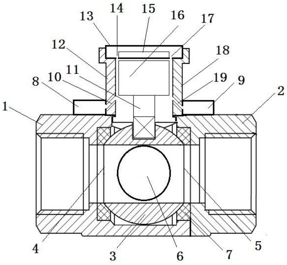
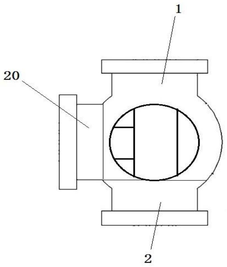
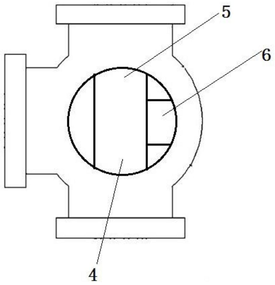
[0047] As shown in the figure: a vehicle-mounted device with a network port conversion chip, which is used to control the flow of fluid in the vehicle. The vehicle-mounted device includes a first distribution valve body, a second distribution valve body, an inflow valve body, a valve core, Sealing seat, first sensing module, second sensing module, transmission shaft, bar, electrical box, control module, motor; wherein the valve core includes a first distribution channel, a second distribution channel, an inflow channel, and a half valve Core one, half spool two, upper embedding ring, lower embedding ring, butt surface, middle cavity, inflow check valve, distribution check valve one, distribution check valve two, upper positioning plate, lower positioning plate; The plate is provided with a first-stage inclined hole, and the lower wall of the electrical box is provided with a second-stage hole;

[0048] The fluid enters the on-board equipment from the inflow valve body, and is ...


PUM


Abstract

Vehicle-mounted equipment with a network port conversion chip comprises a first distribution valve body, a second distribution valve body, an inflow valve body, a valve element, a sealing seat, a first sensing module, a second sensing module, a transmission shaft, a batten, an electrical box and a control module. The control module comprises a single-chip microcomputer, the network port conversion chip and a network communication device. The network port conversion chip transmits signals between the single-chip microcomputer and the network communication device. The network port conversion chip is connected with the single-chip microcomputer through data interfaces, and the data interfaces comprise an 8-bit parallel interface, an SPI interface and an asynchronous serial port. Protocol stack firmware is arranged in the network port conversion chip, a PPPOE protocol is arranged in the protocol stack firmware, and the PPPOE protocol can be used for realizing communication between the network port conversion chip and the network communication device.

Description

technical field [0001] The invention relates to the field of military control vehicle-mounted equipment and electronic chips (international classification number H01), in particular to a vehicle-mounted equipment with a network port conversion chip. Background technique [0002] The main task of centralized management and control equipment is to conduct centralized management, real-time monitoring and comprehensive control of various states and information of public platform equipment. The controlled objects include automobile chassis, information calendar, electric lifting rod, fuel heater, lodging mechanism, Air conditioner, generator set, power wall box, integrated power supply, etc. At present, especially in the field of military use, the requirements for localization and independent control of electronic components such as chips are becoming more and more stringent. The core circuit boards or core electronic components used in centralized control equipment are basically...

Claims


Application Information

Patent Timeline
IPC IPC(8): F16K11/087F16K15/03F16K15/18F16K31/04G05D7/06
CPCF16K11/087F16K15/03F16K31/042G05D7/0635
Inventor 赵柏程李宏王涛莫秋元游洪波黄新勇王章王艳
Owner 衡阳泰豪通信车辆有限公司
Why Eureka
Try Eureka