Hot melting framework for retaining ring of fan

A buckle and hot-melt technology, applied in the magnetic circuit shape/style/structure, electromechanical devices, electrical components, etc., can solve the problems affecting the stability of the buckle 21, the floating of the positioning ring 22, etc., so as to avoid the loosening of the shaft. risk, improve reliability and stability, and ensure the effect of rotation accuracy

Inactive Publication Date: 2021-10-01
江苏嘉之瑞电子科技有限公司
View PDF6 Cites 0 Cited by
  • Summary
  • Abstract
  • Description
  • Claims
  • Application Information

AI Technical Summary

Problems solved by technology

The fan in the prior art mainly includes a fan blade assembly arranged on the outer frame and composed of a magnet, a fan blade assembly and a shaft, and a motor assembly for controlling the stator of the circuit. The circuit controls the conduction of the stator coil to generate internal excitation to make the fan The axis of the leaf assembly around the central axis rotates on the outer frame, and the axis is provided with a limit slot, see the attached figure 1 , the plastic middle tube 16 of the outer frame is provided with an oil-impregnated bearing 19 that matches the shaft center 18, and the top of the oil-impregnated bearing 19 is provided with a snap ring 21 that fits in a limited position with the limit groove 20. , the top of the retaining ring 21 is provided with a positioning ring 22 with an interference fit between the outer wall and the inner wall of the plastic middle tube 16, and the retaining ring 21 is pressed into the oil bearing 19 through the positioning ring 22. The positioning of the frame is fixed and can be rotated under the support of the oil bearing 19. It is fixed only by the interference fit between the buckle 21 and the plastic middle tube 16. The positioning ring 22 floats up or even falls off, which affects the alignment of the buckle 21 to the axis 18. The limit and the stability of the axis 18 operation

Method used


Image

  • Hot melting framework for retaining ring of fan
  • Hot melting framework for retaining ring of fan
  • Hot melting framework for retaining ring of fan

Examples


Embodiment Construction

[0019] The specific embodiments of the present invention will be further described below in conjunction with the accompanying drawings.

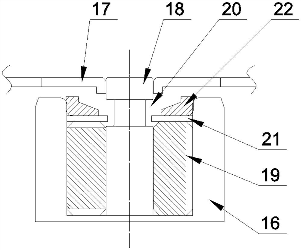
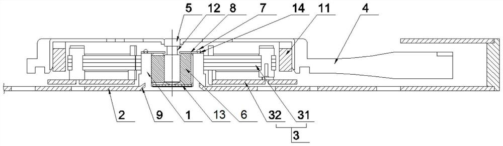
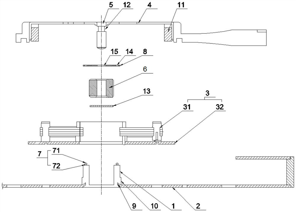
[0020] A fan clasp 8 hot-melt structure, including an outer frame 2 with a plastic inner tube 1, a motor assembly 3, and a fan blade assembly 4. The center of the fan blade assembly 4 is provided with an axis 5, and the axis 5 There is an oil-impregnated bearing 6 with clearance fit between the outer wall and the inner wall of the plastic middle tube 1, wherein the motor assembly 3 is fixed on the outside of the plastic middle tube 1, and the motor assembly 3 includes an injection package stator 31 fixed on the injection The PCBA board 32 at the bottom of the package stator 31, the inner wall of the injection package stator 31 is in interference fit with the outer wall of the plastic middle tube 1, and the outer frame 2 is provided with an oblique setting with the bottom of the outer frame 2 and is integrated with the plastic middle tube 1 by...


PUM


Abstract

The invention relates to a hot melting framework for a retaining ring of a fan. The hot melting framework comprises an outer frame with a plastic middle pipe, a motor assembly and a fan blade assembly, wherein an axis is arranged in the center of the fan blade assembly; an oil bearing is arranged between the outer wall of the axis and the inner wall of the plastic middle pipe; the motor assembly is fixed to the outer portion of the plastic middle pipe; a magnet is arranged on the inner wall of the fan blade assembly; a limiting groove is formed in the axis; hot melting columns are arranged on the top of the plastic middle pipe; the retaining ring matched with the limiting groove in a limiting mode is arranged on the top of the plastic middle pipe and the top of the oil bearing; a plurality of first through holes are formed in the retaining ring; and the hot melting columns penetrate through the corresponding through holes and protrude out of the edge to be connected with the top of the retaining ring in a hot melting mode. The hot melting columns on the plastic middle pipe are connected with the retaining ring in a hot melting mode to package the oil bearing, and the retaining ring is matched with the limiting groove of the axis in a limiting mode, so that the axis and the outer frame of the fan blade assembly are reliably, stably and rapidly positioned and assembled, the cost is reduced, the technology is saved, the risk of axis loosening caused by floating or falling of a positioning ring is avoided, and the reliability and stability of fan operation are improved.

Description

technical field [0001] The invention relates to a heat-melt structure of a fan clasp, which belongs to the technical field of fan structures. Background technique [0002] The fan rotates under the force of the energized coil in the magnetic field, converts the electrical energy into mechanical energy, and turns the airflow generated by the rotation of the fan blade into natural wind to achieve the purpose of cooling, and is widely used. The fan in the prior art mainly includes a fan blade assembly arranged on the outer frame and composed of a magnet, a fan blade assembly and a shaft, and a motor assembly for controlling the stator of the circuit. The circuit controls the conduction of the stator coil to generate internal excitation to make the fan The axis of the leaf assembly around the central axis rotates on the outer frame, and the axis is provided with a limit slot, see the attached figure 1 , the plastic middle tube 16 of the outer frame is provided with an oil-impre...

Claims


Application Information

Patent Timeline
Patent Type & Authority Applications(China)
IPC IPC(8): F04D25/08F04D29/40F04D29/26F04D29/05F04D29/053F04D29/056H02K7/14H02K1/18H02K11/30H02K1/27
CPCF04D25/08F04D29/403F04D29/26F04D29/05F04D29/053F04D29/0563H02K7/14H02K1/187H02K11/30H02K1/2786
Inventor 周效刚
Owner 江苏嘉之瑞电子科技有限公司
Why Eureka
Try Eureka