Distributed grouting system for underground diaphragm wall

A technique for underground diaphragm walls and grouting systems, applied in the field of distributed grouting systems for underground diaphragm walls, can solve the problems of large differences in grouting effects, uneven filling of grouting liquid, and a large number of grouting pipes, etc., to achieve improved The effect of carrying capacity

Active Publication Date: 2021-10-01
南京东土建设科技有限公司 +1
View PDF10 Cites 0 Cited by
  • Summary
  • Abstract
  • Description
  • Claims
  • Application Information

AI Technical Summary

Problems solved by technology

However, the post-grouting construction of the existing underground diaphragm wall needs to arrange a number of pile side and pile bottom grouting pipes in the steel cage. There are many grouting pipes, uneven filling of grouting liquid, and differences in grouting effects at different positions. Major and other issues

Method used


Image

  • Distributed grouting system for underground diaphragm wall
  • Distributed grouting system for underground diaphragm wall
  • Distributed grouting system for underground diaphragm wall

Examples


Embodiment Construction

[0020] The technical solution of the present invention will be further explained below in conjunction with the accompanying drawings.

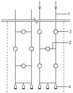
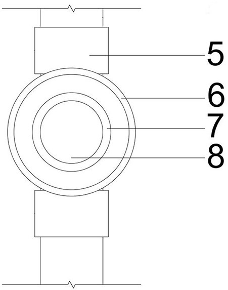
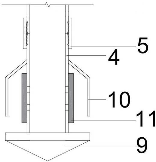
[0021] The distributed grouting system for the underground diaphragm wall is arranged on the outside of the reinforcement cage, and is arranged according to the size of the underground diaphragm wall, such as figure 1 It is a schematic diagram of the overall structure of the distributed grouting system for the underground diaphragm wall of the present invention. The grouting system includes: a grouting vertical pipe 1, a grouting horizontal pipe 2, a wall side grouting head 3, a wall bottom grouting head 4, and a connecting sleeve 5. The first three-way head 14 and the second three-way head; the grouting vertical pipe 1 and the grouting horizontal pipe 2 are evenly distributed in the underground continuous wall, and the grouting vertical pipe 1 and the grouting horizontal pipe 2 are equipped with walls Side grouting head 3, wall bottom groutin...


PUM


Abstract

The invention discloses a distributed grouting system for an underground diaphragm wall. The distributed grouting system comprises a vertical grouting pipe, a transverse grouting pipe, wall side grouting heads, wall bottom grouting heads, connecting sleeves, first tee joints and second tee joints; the vertical grouting pipe and the transverse grouting pipe are evenly distributed in the underground diaphragm wall and provided with the wall side grouting heads and the wall bottom grouting heads respectively; the vertical grouting pipe is connected with the wall side grouting heads through the connecting sleeves and the first tee joints; a grouting operation head is arranged in the vertical grouting pipe; the transverse grouting pipe is connected with the wall side grouting heads through the connecting sleeves and the second tee joints; the wall bottom grouting heads are connected to the bottom end of the vertical grouting pipe and the bottommost transverse grouting pipe through the connecting sleeves and the second tee joints; the wall side grouting heads face the outer side of the wall of the underground diaphragm wall; and the wall bottom grouting heads face the outer side of the wall bottom of the underground diaphragm wall. The distributed grouting system can be suitable for the uniform grouting process of the large-area underground diaphragm wall.

Description

technical field [0001] The invention relates to the technical field of underground diaphragm wall grouting, in particular to a distributed grouting system for an underground diaphragm wall. Background technique [0002] Diaphragm wall is a form of deep foundation with high bearing capacity and low settlement, which is widely used in bridges, major buildings and other projects. The construction of the underground diaphragm wall generally involves measures such as groove formation, lower reinforcement cage and pouring concrete. For deep foundations, the groove depth is generally deep, and mud retaining walls are required to keep the walls intact, which also brings some negative problems, such as the softening of the soil near the hole walls to form mud skins on the wall and soil sides, and The accumulation of sediment at the bottom of the trench is unavoidable during the construction of the trench, and the above problems seriously affect the bearing performance of the undergr...

Claims


Application Information

Patent Timeline
IPC IPC(8): E02D15/02E02D3/12E02D5/18
CPCE02D15/02E02D3/12E02D5/18E02D2250/003
Inventor 靳朋刘朱建民陈祉阳陈新奎魏成孙信锁尹恒龙周传金纯
Owner 南京东土建设科技有限公司
Why Eureka
Try Eureka