
Connector assembly

A technology of connector components and connector modules, which is applied in the direction of connections, components of connection devices, two-part connection devices, etc., can solve problems affecting the normal use of products, affecting product appearance and quality, poor waterproof performance of connector components, etc. , to achieve the effect of improving appearance and quality, and good waterproof performance

Pending Publication Date: 2021-09-28
HENGNAN DEYI PRECISION ELECTRONICS IND
View PDF1 Cites 0 Cited by
  • Summary
  • Abstract
  • Description
  • Claims
  • Application Information

AI Technical Summary

Problems solved by technology

[0003] However, due to the small contact range between the support part and the second fixing part, the support part is easy to slip out of the groove after repeated insertions, and the first fixing part loses all When the support part is against it towards the shielding shell, the separation between the first fixing part and the shielding shell is likely to occur due to external force or cooling shrinkage factors, resulting in the inner shell and the shielding shell. Openings are created between the shielding shells, the waterproof performance of the connector assembly is poor, and dust or other foreign objects are likely to enter between the inner shell and the connector module, which affects the normal use of the product and affects the appearance of the product and quality

Method used


Image

  • Connector assembly
  • Connector assembly
  • Connector assembly

Examples


Embodiment Construction

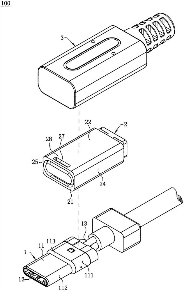
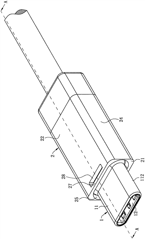
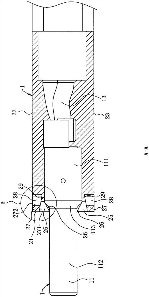
[0029] In order to facilitate a better understanding of the purpose, structure, features and functions of the present invention, the connector assembly 100 of the present invention will be further described in conjunction with the accompanying drawings and specific embodiments.

[0030] Such as figure 1 As shown, it is an exploded perspective view of the inventive connector assembly 100 , the connector assembly 100 includes a connector module 1 , a first shell 2 and a second shell 3 . In this embodiment, the connector module 1 includes an insulating body 12, a plurality of terminals (not shown, the same below), a metal shell 11 and a cable 13, and a plurality of the terminals are fixed on the The insulating body 12 is electrically connected to the cable 13 . The insulating body 12 is accommodated in the metal shell 11, and the metal shell 11 includes a base 111 and a pair of docking parts 112 extending from the base 111 for docking with a mating connector (not shown). The ou...


PUM


Abstract

The invention discloses a connector assembly. The connector assembly comprises a connector module, a first shell and a second shell,; the first shell is located outside the connector module, the first shell is provided with a first groove and a second groove, and the first groove is communicated with the second groove; the first shell is provided with a first fixing part and a second fixing part, the first fixing part is close to the connector module relative to the second fixing part, and the second fixing part is provided with a first abutting surface and a second abutting surface; the first abutting surface forms a part of the first groove, and the second abutting surface forms a part of the second groove; the second shell is formed outside the first shell in an injection molding mode, the second shell is provided with at least one buckling part which fills the first groove and the second groove, the buckling part abuts against the first fixing part in the direction close to the connector module, and the buckling part abuts against the first abutting face and the second abutting face at the same time; and the included angle between the direction in which the buckling part abuts against the first abutting face and the direction in which the buckling part abuts against the second abutting face is smaller than 180 degrees, so that the buckling part stably abuts against the first fixing part, and no opening is generated between the first shell and the connector module.

Description

【Technical field】 [0001] The invention relates to a connector assembly, in particular to a connector assembly in which shells are closely combined. 【Background technique】 [0002] The Chinese application number is CN201911027709.X, which discloses that in the manufacture of existing electronic modules, a plurality of terminals are usually embedded in an insulating body, and a shielding shell frame is used to surround the insulating body, and then injection molding In this way, an inner shell and an outer shell are arranged outside the shielding shell to provide insulating and grippable parts. Since the shielding shell is generally made of metal, and the inner shell and the outer shell are made of plastic, when the inner shell and the outer shell are molded outside the shielding shell by injection molding, it is easy to insert Openings are formed between the inner shell and the shielding shell, and between the outer shell and the shielding shell. Therefore, a groove is prov...

Claims


Application Information

Patent Timeline
IPC IPC(8): H01R13/504H01R13/52
CPCH01R13/504H01R13/5202H01R13/521H01R13/405H01R43/18Y02E60/10H01R13/516H01R24/60H01R13/514
Inventor 邹小乐
Owner HENGNAN DEYI PRECISION ELECTRONICS IND
Learn More