
Photoresist coating device and method

A coating device and photoresist technology, applied in optics, optomechanical equipment, photo-engraving process coating equipment, etc., can solve the problem of uneven coating thickness of photoresist, improve coating uniformity, prevent overflow , easy to operate effect

Inactive Publication Date: 2021-09-28
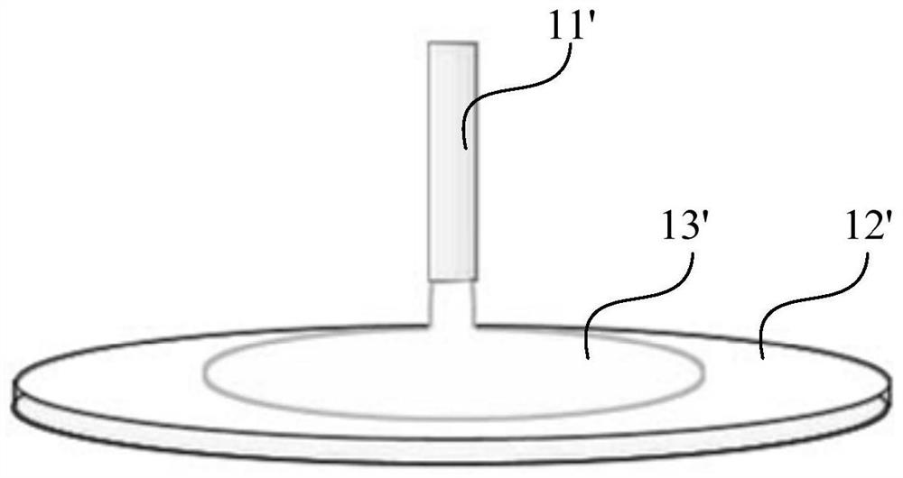
CHANGXIN MEMORY TECH INC
View PDF6 Cites 0 Cited by
  • Summary
  • Abstract
  • Description
  • Claims
  • Application Information

AI Technical Summary

Problems solved by technology

[0006] Embodiments of the present invention provide a photoresist coating device and method to solve the problem of uneven thickness of photoresist coating

Method used


Image

  • Photoresist coating device and method
  • Photoresist coating device and method
  • Photoresist coating device and method

Examples


Embodiment Construction

[0023] The present invention will be further described in detail below in conjunction with the accompanying drawings and embodiments. It should be understood that the specific embodiments described here are only used to explain the present invention, but not to limit the present invention. In addition, it should be noted that, for the convenience of description, only some structures related to the present invention are shown in the drawings but not all structures.

[0024] An embodiment of the present invention provides a photoresist coating device, including:

[0025] The liquid gasification module is used to convert the liquid photoresist into gaseous photoresist and transport it to the photoresist coating module;

[0026] The photoresist coating module includes: a vapor coating unit, a cover plate and a carrier table;

[0027] The steam coating unit includes a steam channel and a steam injection hole; the steam injection hole is set through the cover plate; the carrying p...


PUM

PropertyMeasurementUnit
sizeaaaaaaaaaa
sizeaaaaaaaaaa
sizeaaaaaaaaaa

Abstract

The invention discloses a photoresist coating device and method, wherein the photoresist coating device comprises a liquid gasification module which is used for converting liquid photoresist into gaseous photoresist and conveying the gaseous photoresist to a photoresist coating module; the photoresist coating module comprises a steam coating unit, a cover plate and a bearing table; the steam coating unit comprises a steam channel and a steam spraying hole; the steam spraying holes penetrate through the cover plate; the bearing table is used for loading a substrate; the cover plate is arranged on the side, close to the substrate, of the bearing table; and the steam coating unit obtains the gaseous photoresist through the steam channel, and conveys the gaseous photoresist to a to-be-coated surface of the substrate on the bearing table through the steam spray holes to form a photoresist coating layer. The invention provides a photoresist coating device and method, and aims to solve the problem of non-uniform photoresist coating thickness.

Description

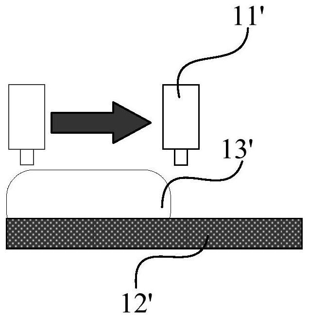
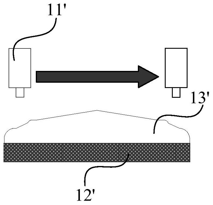
technical field [0001] The invention relates to the technical field of semiconductor photolithography, in particular to a photoresist coating device and method. Background technique [0002] Photoresist (Photoresist, PR), also known as photoresist, often needs to use a coating machine to coat photoresist on a substrate during the manufacturing process of display products. [0003] In the related art, the photoresist coating machine includes a turntable and a nozzle. The turntable has a bearing surface. The glue is spin-coated on the substrate, and finally a photoresist layer is formed on the substrate. [0004] specific, figure 1 is a structural schematic diagram of a photoresist coating machine in the prior art, in the prior art, such as figure 1 As shown, the photoresist coating machine includes a turntable 12' and a nozzle 11'. The turntable 12' has a carrying surface, and the carrying surface is used to place a substrate to be coated with photoresist 13', and the phot...

Claims


Application Information

Patent Timeline
Patent Type & Authority Applications(China)
IPC IPC(8): G03F7/16
CPCG03F7/16G03F7/167H01L21/6715G03F7/162H01L21/67017
Inventor 吴明锋
Owner CHANGXIN MEMORY TECH INC
Learn More