Slab end slotted hole SP hollow laminated slab-steel beam connecting structure and construction method thereof

A technology of connecting structures and slotting holes, which is applied to floors, building components, building structures, etc., can solve problems such as poor structural integrity and seismic performance, brittle damage at the joints of plate ends, and unreasonable structural force transmission, etc., to achieve Reduce construction difficulty, reduce mid-span deflection, and ensure continuity and integrity

Pending Publication Date: 2021-09-28
NANJING UNIV OF AERONAUTICS & ASTRONAUTICS
View PDF6 Cites 2 Cited by
  • Summary
  • Abstract
  • Description
  • Claims
  • Application Information

AI Technical Summary

Problems solved by technology

However, this traditional connection form does not give full play to the combined effect of steel beams and concrete, and the structural force transmission is unreasonable. Only relying on welding connection is prone to brittle failure at the plate end connection. Shear failure often occurs at the end of the slab under load, and the integrity and seismic performance of the structure are poor. It is often only suitable for low-rise buildings with low requirements for mechanical performance and seismic performance.
[0006] With the rapid growth of my country's economy and social progress, today's prefabricated buildings are developing in the direction of high-rise, heavy-duty, and large-span. The traditional slab end beam-slab connection can no longer meet the current needs. Therefore, it is necessary to explore a A new form of SP prestressed hollow laminated slab composite floor beam-slab connection

Method used


Image

  • Slab end slotted hole SP hollow laminated slab-steel beam connecting structure and construction method thereof
  • Slab end slotted hole SP hollow laminated slab-steel beam connecting structure and construction method thereof
  • Slab end slotted hole SP hollow laminated slab-steel beam connecting structure and construction method thereof

Examples


Embodiment Construction

[0034] The present invention will be further described below in conjunction with accompanying drawing.

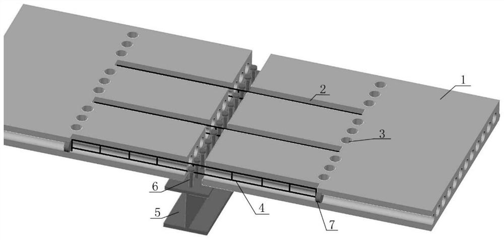
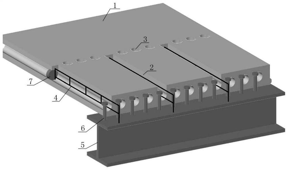
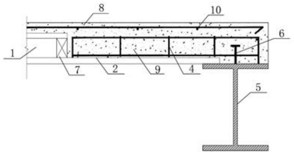
[0035] The SP prestressed hollow laminated slab combined floor beam-slab connection structure provided by the present invention mainly includes a SP prestressed hollow slab 1, a longitudinal reinforcement grid 4, a steel beam 5, a shear connector 6, Post-cast concrete layer 8, such as figure 1 , figure 2 , image 3 and Figure 4 shown.

[0036] Open the plate end groove 2 at the 1 / 4 core hole of the upper plate end of the SP prestressed hollow plate 1, and open the plate top hole 3 at the remaining core holes, and the opening position is aligned with the slot length, such as figure 1 , figure 2 and Figure 5 shown.

[0037] Set up the longitudinal steel grid frame 4 at the groove 2 of the plate end, and when it is a beam-slab connection at the side beam, it is spot welded and fixed with the steel beam 5 on site, such as figure 1 , figure 2 , image 3 and Figu...


PUM


Abstract

The invention provides a slab end slotted hole SP hollow laminated slab-steel beam connecting structure and a construction method thereof. The slab end slotted hole SP hollow laminated slab-steel beam connecting structure is composed of an SP prestressed hollow slab with a slab end core hole slotted hole and a slab top hole, a steel bar net rack, a shearing force connecting piece and a post-pouring concrete layer. The slab end of the prefabricated SP prestressed hollow slab is provided with an elongated slot, the slab top hole is formed, the steel bar net rack is placed in the slot, the shearing force connecting piece is welded to a steel beam, and the slab end elongated slot and core hole are filled when the concrete post-pouring layer is poured. The effective width of slab ribs can be increased by filling the slab end core holes with the concrete, the slab end shear bearing capacity can be improved, the weak part of the slab is reinforced, the longitudinal continuity and integrity of the floor slab can be guaranteed through the steel bar net rack, part of hogging moment can be borne under the vertical load, the midspan deflection of the composite floor system is reduced, the vertical bearing capacity is improved, the steel bar can be used as a longitudinal shear-resistant steel bar of a composite beam and a slab-end shear-resistant steel bar to enhance the slab-end shear-resistant bearing capacity, and a wide application prospect is achieved.

Description

technical field [0001] The invention relates to the field of building structures, in particular to a SP hollow laminated plate-steel beam connection structure with slotted holes at the plate end and a construction method thereof. Background technique [0002] The steel-concrete composite floor is a composite structure formed by combining steel beams and concrete floors. It can save the amount of steel used and reduce the height of the structure. Due to its light weight, it is beneficial to the seismic performance of the main structure. At the same time, it can also reduce the difficulty of foundation treatment and reduce the cost of the project. It is an important structural system for the development of prefabricated buildings. [0003] As a structural form of steel-concrete composite floors, laminated slab composite floors do not require formwork during construction, and prefabricated concrete slabs are directly hoisted on site after being processed by the factory, which g...

Claims


Application Information

Patent Timeline
Patent Type & Authority Applications(China)
IPC IPC(8): E04B5/38E04B5/29
CPCE04B5/38E04B5/29
Inventor 陈娟谢科吴浩胡顺杰张仁杰
Owner NANJING UNIV OF AERONAUTICS & ASTRONAUTICS
Why Eureka
Try Eureka