
Plate loading and unloading device

A loading and unloading device and sheet material technology, applied in the direction of transportation and packaging, conveyor objects, support frames, etc., to achieve the effects of improving processing efficiency, personal safety protection, and improving loading and unloading efficiency

Pending Publication Date: 2021-09-28
安徽中科春谷激光产业技术研究院有限公司
View PDF0 Cites 0 Cited by
  • Summary
  • Abstract
  • Description
  • Claims
  • Application Information

AI Technical Summary

Problems solved by technology

[0003] Aiming at the problem that the existing sheet material loading and unloading needs to rely on manual handling, which is time-consuming and laborious and has certain personal safety problems, the present invention provides a sheet material loading and unloading device. By setting the first slide rail, the second slide rail and the linkage rod, Through the linkage between these components, the sheet metal handling device can complete the loading, unloading and transfer of materials between the sheet metal and the machine tool, which greatly saves manpower and greatly improves the loading and unloading safety of the sheet material handling device. To solve the problems raised in the background technology

Method used


Image

  • Plate loading and unloading device
  • Plate loading and unloading device
  • Plate loading and unloading device

Examples


Embodiment 1

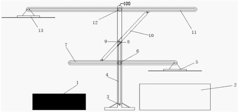
[0026] like figure 1 As shown, it is a structural schematic view of a sheet handling device according to a preferred embodiment of the present invention, and the sheet handling device 100 of the present embodiment includes a first slide rail 7 and a second sliding rail 11, the first slippery The rail 7 and the second sliding rail 11 are coupled by a linkage connection, and the first slide rail 7 and the second slide rail 11 are respectively provided with a first electromagnetic suction cup 5 and a second electromagnetic suction cup 13, respectively. The loading and unloading and transportation of the sheet is performed by fitting the first electromagnetic suction cup 5 and the second electromagnetic chuck 13.

[0027] The left and right sides of the sheet handling device 100 are respectively disposed as sheets 1 and machine 2, and the lower end of the sheet handling device 100 is provided with a motor 3, and the motor 3 is fixedly connected to the sheet loading and unloading devic...

Embodiment 2

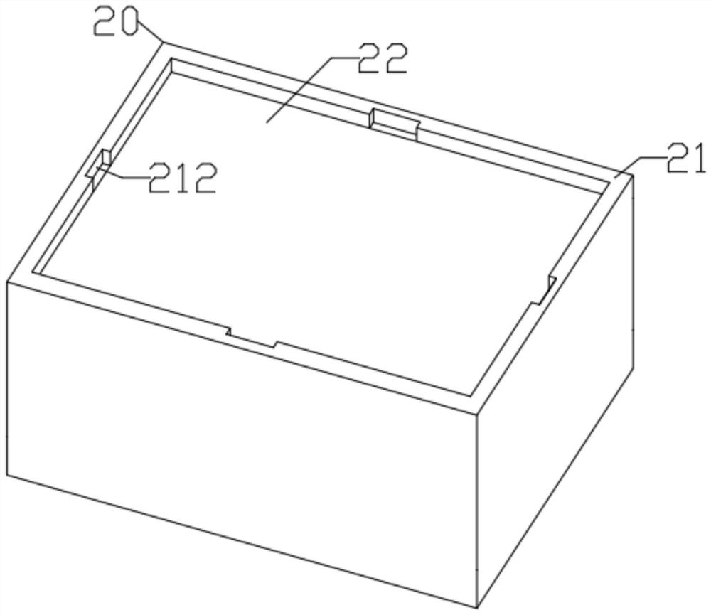
[0033] like Figure 2 ~ 5 As shown, it is a schematic structural diagram of a sheet handling device according to another preferred embodiment of the present invention, and the sheet handling device 100 of the present embodiment is provided on the basis of Example 1, and the sheet placing box 20 is provided. The sheet 1 is placed and the height adjustment allows the height of the sheet 1 to always fits the sheet loading and unloading device 100 for the loading and unloading of the sheet 1.

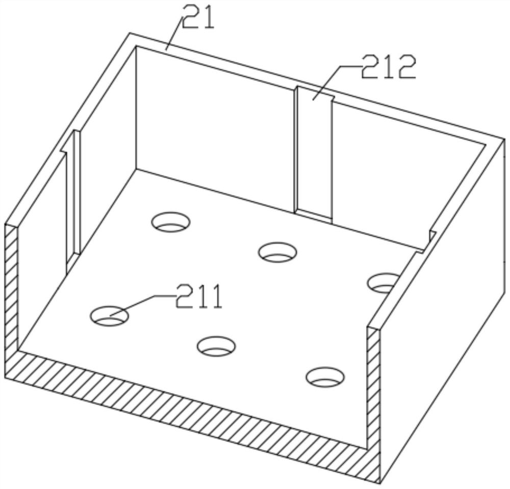
[0034] The sheet placing tank 20 includes a casing 21, a sheet plate 22, and a tough spring 23, and a spring mounting groove 211 is provided on the bottom plate of the casing 21, which is used to mount toughness. The spring 23 is provided with a sliding positioning groove 212 on the four-week inner wall of the casing 21, which is used to connect the mounting sheet placement plate 22.

[0035] A sliding positioning block 221 is provided on the four-week outer wall of the sheet plate 22, and the s...


PUM


Abstract

The invention discloses a plate loading and unloading device, and belongs to the technical field of plate loading and unloading devices. A first sliding rail, a second sliding rail and a linkage rod are arranged, and loading, unloading and conversion conveying of materials between plates and a machine tool can be completed by the plate loading and unloading device through linkage matching among the components, so that the manual labor is saved to a great extent, and the loading and unloading safety of the plate loading and unloading device is greatly improved; and the plate placing height is adjusted by arranging a plate placing box, the plate placing box comprises a box body, a plate placing plate and a toughness spring, and through cooperative use of the components, a plate can be automatically lifted to a set position when being taken, so that the loading and unloading work of the plate loading and unloading device can be normally operated, the loading and unloading efficiency of the plate loading and unloading device can be improved in cooperation with use of the plate loading and unloading device; and the plate processing efficiency of the plate loading and unloading device is improved to a great extent.

Description

Technical field [0001] The present invention belongs to the technical field of sheet loading and unloading device, and in particular, it is directed to a sheet handling device. Background technique [0002] A sheet of sheets need to be transported from the machining area to the machine to process the sheet to process the sheet, and the discharge and handling of unloading in the traditional all-generation, and passed through the turnover to the processing zone Whether it is loading or unloading or transportation, it is very expensive and even bringing certain personal safety issues. With the progress of the times and the development of science and technology, in order to save labor, reduce personnel casualties, in soon In the future, all instruments, equipment will go to automation, and the traditional industry will gradually replace the automated industrial, and the design of the present invention is mainly for the loading and unloading and loading of small and medium-sized sheet...

Claims


Application Information

Patent Timeline
IPC IPC(8): B65G47/92B65G41/00
CPCB65G47/92B65G41/003
Inventor 潘雄飞
Owner 安徽中科春谷激光产业技术研究院有限公司
Learn More