Convenient and fast cutting equipment for energy-saving and environment-friendly materials

A cutting equipment, energy-saving and environment-friendly technology, applied in metal processing, etc., can solve the problems of difficult walls and edge parts that are difficult to cut flat, fit, etc., and achieve good cutting results

Pending Publication Date: 2021-09-28
林巧静
View PDF4 Cites 0 Cited by
  • Summary
  • Abstract
  • Description
  • Claims
  • Application Information

AI Technical Summary

Problems solved by technology

[0004] Aiming at the disadvantage that the edge part is difficult to cut flat when cutting manually, so that it is difficult to fit the wall when filling, it is necessary to provide a convenient cutting equipment for energy-saving and environmentally friendly materials that does not require manual cutting and has a flat cutting surface.

Method used


Image

  • Convenient and fast cutting equipment for energy-saving and environment-friendly materials
  • Convenient and fast cutting equipment for energy-saving and environment-friendly materials
  • Convenient and fast cutting equipment for energy-saving and environment-friendly materials

Examples


Embodiment 1

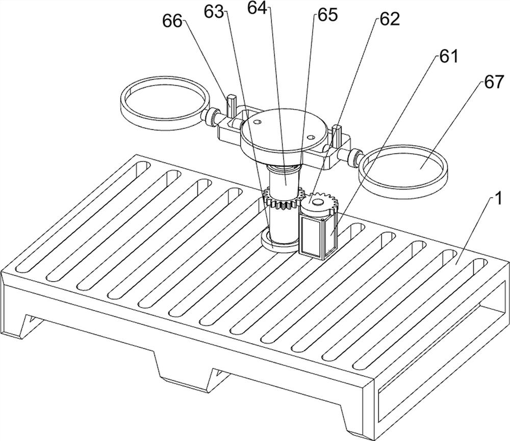
[0024] A convenient cutting equipment for energy-saving and environment-friendly materials, see figure 1 As shown, it includes a base 1, a first mounting seat 2, a guide column 3, a cutting disc 4, a cutting mechanism 5, and a rotating mechanism 6. The left rear side of the top of the base 1 is provided with a first mounting seat 2, and the top of the first mounting seat 2 is There is a guide post 3 on the left side, a cutting disc 4 is slidingly arranged on the guide post 3, a cutting mechanism 5 is connected between the first installation seat 2, the guide post 3 and the cutting disc 4, and a rotating disc is provided in the middle of the top rear side of the base 1. Institution 6.

[0025] refer to figure 2 As shown, the cutting mechanism 5 includes a first spring 51, a first wedge block 52, a support rod 53 and a tray 54, a first spring 51 is connected between the cutting disc 4 and the guide post 3, and a second spring 51 is arranged in the middle of the cutting disc 4 ...

Embodiment 2

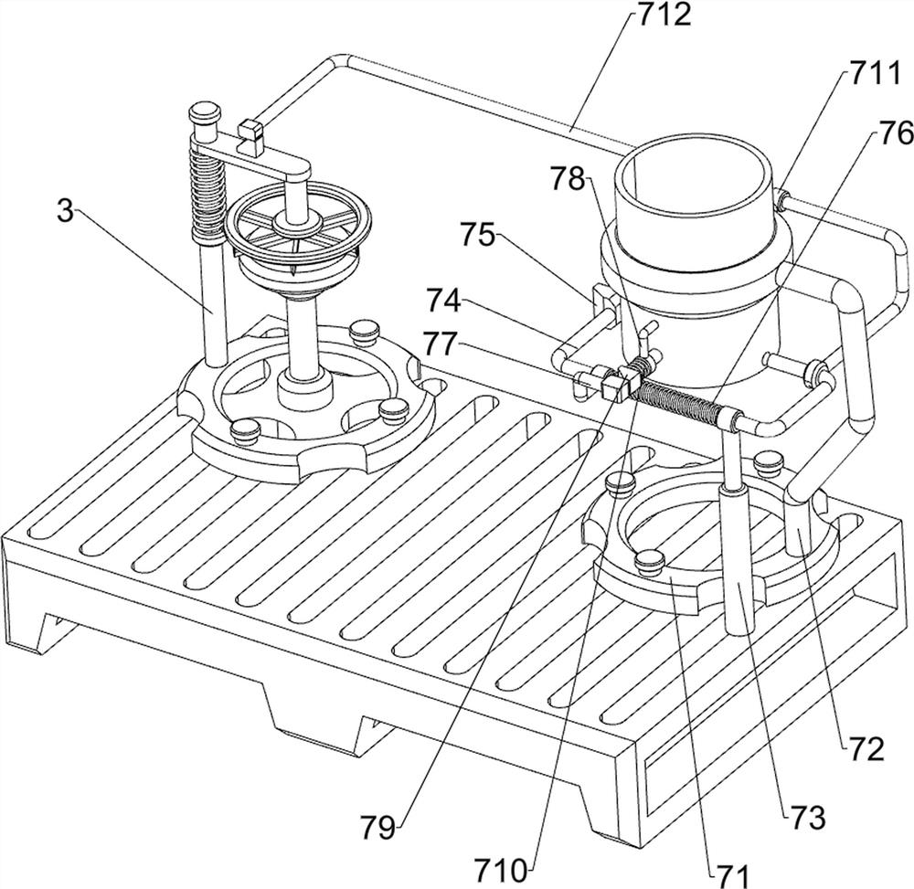
[0029] On the basis of embodiment 1, refer to Figure 4 As shown, a feeding mechanism 7 is also included, and the feeding mechanism 7 includes a second mounting seat 71, a material guide barrel 72, a first sliding sleeve 73, a first extruding rod 74, a second wedge block 75, a second spring 76. Push block 77, second sliding sleeve 78, second extruding rod 79, third spring 710, third sliding sleeve 711 and third extruding rod 712, the second mounting seat 71 is provided on the right rear side of the top of base 1 , the top right side of the second mounting seat 71 is provided with a guide barrel 72, the top right side of the base 1 is provided with a first sliding sleeve 73, and the upper side of the first sliding sleeve 73 is slidingly provided with a first extrusion rod 74, the first extrusion The left side of the compression rod 74 is provided with a second wedge block 75, the second spring 76 is connected between the first extrusion rod 74 and the first sliding sleeve 73, t...


PUM


Abstract

The invention relates to cutting equipment, in particular to convenient and fast cutting equipment for energy-saving and environment-friendly materials. Aiming at the defects in the prior art, the convenient and fast cutting equipment for energy-saving and environment-friendly materials which does not need manual cutting and is flat in cutting surface is provided. According to the technical scheme, the convenient and fast cutting equipment for the energy-saving and environment-friendly materials comprises a base, a first mounting base, a guide column, a cutting disc, a cutting mechanism and a rotating mechanism, the first mounting base is arranged on one side of the top of the base, the guide column is arranged on one side of the top of the first mounting base, and the cutting disc is slidably arranged on the guide column; the cutting mechanism is connected among the first mounting base, the guide column and the cutting disc, and the rotating mechanism is arranged in the middle of one side of the top of the base. Automatic feeding work of materials can be achieved through an arranged feeding mechanism; and through an arranged discharging mechanism, workers do not need to take down the materials in the rotating process of the rotating disc.

Description

technical field [0001] The invention relates to a cutting device, in particular to a convenient cutting device for energy-saving and environment-friendly materials. Background technique [0002] When laying the floor, it is often necessary to lay a layer of filler on the moisture-proof layer first. When laying the filler, sometimes a whole piece of filler cannot be placed near the wall, so it is necessary to cut such materials and cut them into small pieces. Then the filling work is carried out. At present, the staff directly use tools such as cutters to cut the material. However, when cutting manually, the edge part is difficult to cut flat, so it is difficult to fit the wall when filling. [0003] Therefore, it is necessary to design a convenient cutting device for energy-saving and environmentally friendly materials that does not require manual cutting and has a smooth cut surface. Contents of the invention [0004] Aiming at the disadvantage that the edge part is diff...

Claims


Application Information

Patent Timeline
IPC IPC(8): B26D1/09B26D7/01B26D7/06B26D5/08B26D7/32
CPCB26D1/09B26D7/01B26D7/06B26D5/08B26D7/32
Inventor 林巧静
Owner 林巧静
Why Eureka
Try Eureka