
Manufacturing device for anti-skid stripes of industrial foot mats

A technology for manufacturing devices and foot pads, which is applied in positioning devices, manufacturing tools, metal processing equipment, etc., and can solve problems such as difficult anti-skid marks and increased difficulty

Pending Publication Date: 2021-03-26
梁喜先
View PDF4 Cites 0 Cited by
  • Summary
  • Abstract
  • Description
  • Claims
  • Application Information

AI Technical Summary

Problems solved by technology

[0004] In order to overcome the shortcomings that the foot pad has a certain thickness, it is more difficult to cut, and it is not easy to directly cut a complete anti-skid pattern during manual cutting, which affects the use. The technical problem to be solved is to provide a kind of foot pad clip Tight, can make a complete anti-slip pattern on the foot mat An industrial foot mat anti-slip pattern making device

Method used


Image

  • Manufacturing device for anti-skid stripes of industrial foot mats
  • Manufacturing device for anti-skid stripes of industrial foot mats
  • Manufacturing device for anti-skid stripes of industrial foot mats

Examples


Embodiment 1

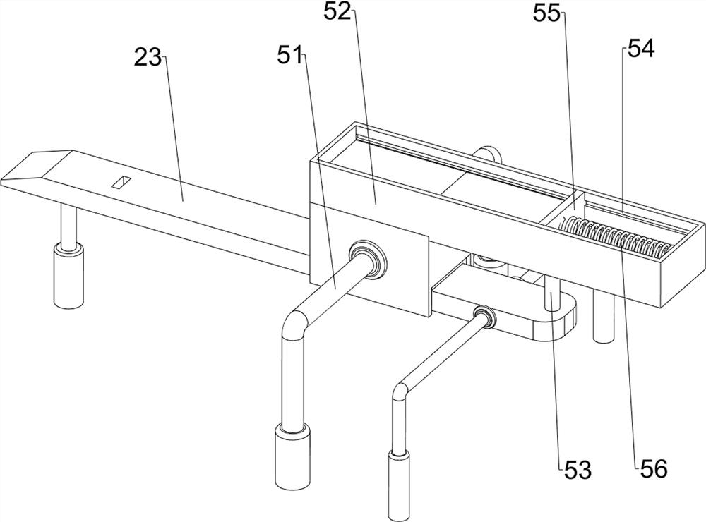
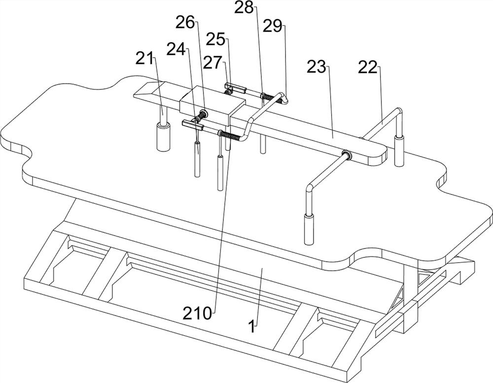
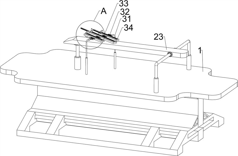
[0086] A device for making anti-slip patterns on industrial foot pads, such as figure 1 As shown, it includes a mounting base 1, a clamping mechanism 2 and a slotting mechanism 3. The clamping mechanism 2 is provided on the top of the mounting base 1, and the slotting mechanism 3 is provided on the left side of the top of the mounting base 1.

[0087] Such as figure 2 As shown, the clamping mechanism 2 includes a first mounting column 21, a second mounting column 22, a sliding plate 23, a first sliding sleeve 24, a first wedge block 25, a clamping plate 26, a first spring 27, and a second sliding sleeve 28. , a push rod 29 and a second spring 210, the left side of the top of the mounting seat 1 is provided with a first mounting column 21, the right side of the top of the mounting seat 1 is symmetrically provided with a second mounting column 22, and the second mounting column 22 and the first mounting column 21 tops are connected with a slide plate 23, and the left side of t...

Embodiment 2

[0091] On the basis of Example 1, such as Figure 5 As shown, it also includes a stopper mechanism 4, and the stopper mechanism 4 includes a third sliding sleeve 41, a stopper block 42, a seventh spring 43, a second wedge block 44, a fourth sliding sleeve 45, a supporting plate 46, a first Eight springs 47 and vertical plate 48, the left side of slide plate 23 bottoms are provided with the 3rd sliding sleeve 41, the sliding type in the 3rd sliding sleeve 41 is provided with retaining block 42, is connected between the retaining block 42 and the 3rd sliding sleeve 41 The seventh spring 43, the second wedge-shaped block 44 is provided at the bottom of the material retaining block 42, the fourth sliding sleeve 45 is provided on the left side of the top of the mounting seat 1, and the fourth sliding sleeve 45 is slidably provided with a supporting plate 46, and the supporting plate 46 and An eighth spring 47 is connected between the fourth sliding sleeves 45 , and a vertical plate...


PUM


Abstract

The invention relates to an anti-skid stripe manufacturing device, in particular to a manufacturing device for anti-skid stripes of industrial foot mats. The technical problem to be solved is to provide the manufacturing device for the anti-skid stripes of the industrial foot mats, which can clamp the foot mat and can form complete anti-skid stripes on the foot mat. According to the technical scheme, the manufacturing device for the anti-skid stripes of the industrial foot mats comprises a mounting base, and a grooving mechanism, wherein a clamping mechanism is arranged on the mounting base; and the grooving mechanism is arranged on one side of the top of the mounting base. The foot mat can be clamped through the arranged clamping mechanism when the foot mat is subjected to anti-skid stripe forming work; the anti-skid stripe forming work is facilitated; and the position of the foot mat can be positioned through an arranged material blocking mechanism, so that the formed anti-skid stripes do not deviate.

Description

technical field [0001] The invention relates to an anti-slip pattern production device, in particular to an anti-slip pattern production device for industrial foot pads. Background technique [0002] In modern society, there are many facilities with pedals, such as machine tools, exercise equipment and bicycles. The surface of the pedals is usually smooth. When the pedals are placed in such facilities, it is not conducive to people to step on them. This is not conducive to ongoing work, exercise or travel, so it is necessary to add foot pads to it, and it is necessary to open anti-skid lines when making the foot pads. At present, it is done manually using a cutter on the foot pads. Cutting, but the foot pad has a certain thickness, so it is more difficult to cut, and it is not easy to directly cut a complete anti-skid pattern during manual cutting, which will affect the use. [0003] Therefore need to design a kind of foot pad that can be clamped, the industrial foot pad an...

Claims


Application Information

Patent Timeline
Patent Type & Authority Applications(China)
IPC IPC(8): B23D79/00B23Q3/06B23Q11/00
CPCB23Q3/062B23Q11/00B23D79/00
Inventor 梁喜先
Owner 梁喜先
Learn More