
Steel pipe internal polishing machine and polishing method thereof

A technology for steel pipes and pipe fittings, which is applied in the field of steel pipe internal polishing machine and its polishing, can solve the problems of increasing the surface scratches of pipe fittings, reducing product production quality, reducing polishing effect, etc., so as to achieve improved polishing effect, good economic and social benefits, The effect of avoiding environmental pollution

Active Publication Date: 2021-09-28
晋义机械设备(上海)有限公司
View PDF7 Cites 1 Cited by
  • Summary
  • Abstract
  • Description
  • Claims
  • Application Information

AI Technical Summary

Problems solved by technology

[0006] In view of the above-mentioned shortcomings of the prior art, the purpose of the present invention is to provide a steel pipe internal polishing machine, which is used to solve the internal polishing equipment existing in the prior art The current clamping mechanism usually places the pipe fittings on the bracket manually, and then performs manual construction pressure or uses a heavy pressure plate to press the pipe fittings, which not only increases labor costs, time-consuming and labor-intensive, but also increases the scratches on the surface of the pipe fittings. And there will still be vibration during the polishing process, thereby reducing the polishing effect and the production quality of the product; and the polishing rod is inserted into the pipe wall, and the polishing rod is driven to rotate by hand or by a motor, and different pipe diameters The inner wall of the pipe fittings is not well polished, and often some subtle places are not polished in place, resulting in poor overall polishing effect

Method used


Image

  • Steel pipe internal polishing machine and polishing method thereof
  • Steel pipe internal polishing machine and polishing method thereof
  • Steel pipe internal polishing machine and polishing method thereof

Examples


Embodiment Construction

[0072] The implementation of the present invention will be illustrated by specific specific examples below, and those skilled in the art can easily understand other advantages and effects of the present invention from the contents disclosed in this specification.

[0073] see Figure 1 to Figure 12 . It should be noted that the structures, proportions, sizes, etc. shown in the drawings attached to this specification are only used to match the content disclosed in the specification, for those who are familiar with this technology to understand and read, and are not used to limit the implementation of the present invention. Limiting conditions, so there is no technical substantive meaning, any modification of structure, change of proportional relationship or adjustment of size, without affecting the effect and purpose of the present invention, should still fall within the scope of the present invention. The disclosed technical content must be within the scope covered. At the s...


PUM


Abstract

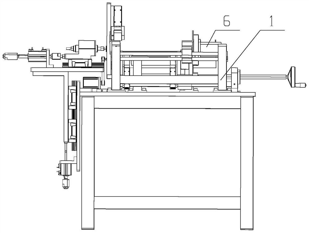
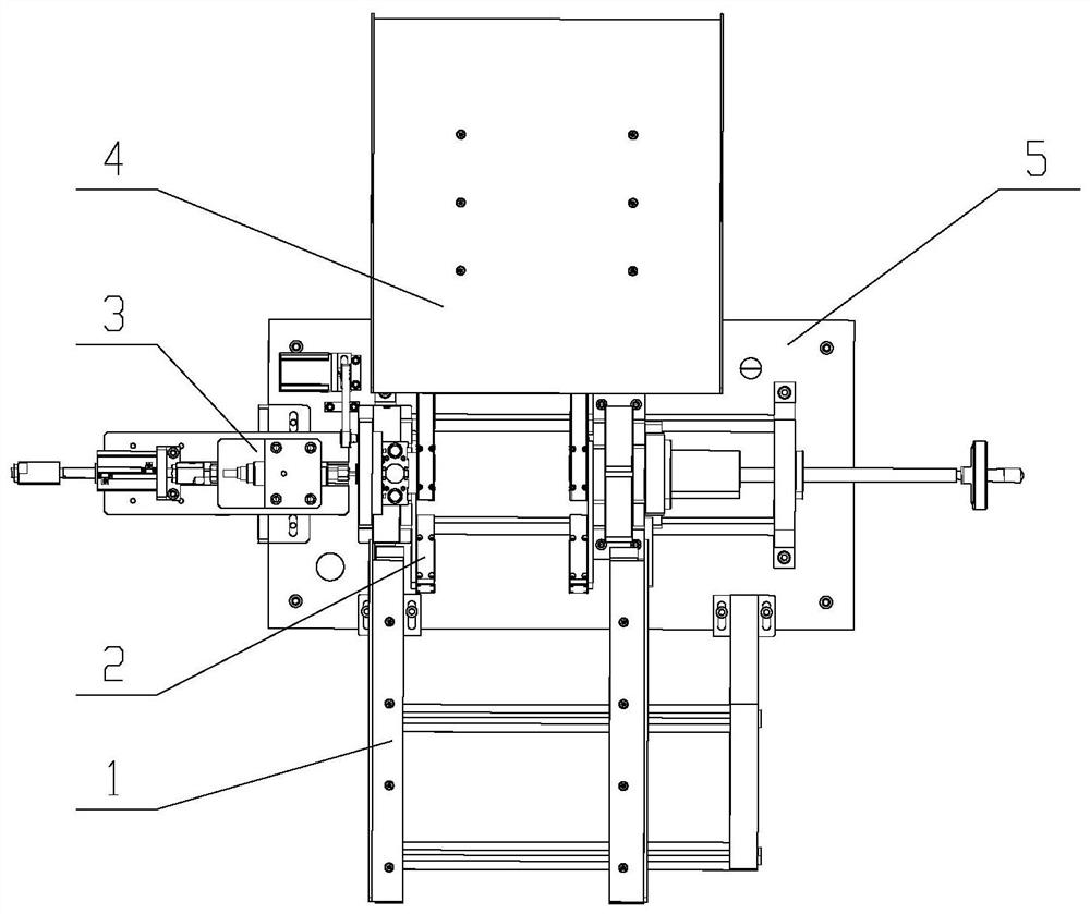
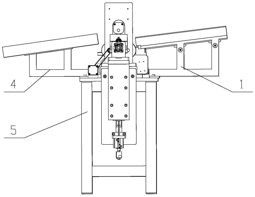
The invention provides a steel pipe internal polishing machine and a polishing method thereof. A feeding and discharging mechanism is arranged on one side of the top of a supporting base, a laying-off and discharging mechanism is arranged on the other side of the top of the supporting base, a rotary supporting mechanism is arranged between the feeding and discharging mechanism and the laying-off and discharging mechanism, and a clamping device is arranged on the rotary supporting mechanism; and the clamping device clamps a to-be-polished pipe fitting and drives the to-be-polished pipe fitting to rotate, a dust removal mechanism is arranged on one side of the rotary supporting mechanism, and a scrap removal polishing mechanism is arranged on the other side of the rotary supporting mechanism and comprises a scrap removal polishing head and a feeding mechanism. The scrap removal polishing head is located in a pipe of the to-be-polished pipe fitting and is driven by the feeding mechanism to move in the length direction of the to-be-polished pipe fitting. By means of the steel pipe internal polishing machine and the polishing method thereof, steel pipes with different diameters can be supported, the height of the scrap removal polishing head can be adjusted, the applicability to to-be-polished pipe fittings with different pipe diameters and the precision consistency during scrap removal polishing are achieved, the polishing efficiency is high, the service life is long, and environmental pollution is avoided.

Description

technical field [0001] The invention belongs to the technical field of steel pipe production, and in particular relates to a steel pipe internal polishing machine and a polishing method thereof. Background technique [0002] Pipe parts have good mechanical properties and corrosion resistance, and are widely used in aerospace, marine, nuclear energy, medical equipment, petrochemical and other fields. Pipe parts have good corrosion resistance and are mainly used for fluid delivery pipes for high-end products. In recent years, with the development and innovation of technology, people's demand for pipe parts is increasing day by day, and their quality requirements are also increasing. Since reducing the roughness of the inner wall of the pipe fitting can reduce the resistance of the inner wall to the fluid and the adsorption effect of the material on the inner wall, people have higher and higher requirements for the roughness of the inner wall of the pipe fitting. In the early ...

Claims


Application Information

Patent Timeline
Patent Type & Authority Applications(China)
IPC IPC(8): B24B29/08B24B41/00B24B41/06B24B47/12B24B47/20B24B47/22B24B55/06
CPCB24B29/08B24B41/067B24B47/12B24B47/22B24B47/20B24B55/06B24B41/005
Inventor 张义喜徐军军
Owner 晋义机械设备(上海)有限公司
Learn More