
Boiler flue gas multi-point drainage mixing detection device

A boiler flue gas and detection device technology, which is applied in the direction of measuring devices, analyzing gas mixtures, sampling devices, etc., can solve the problems of endangering the safety of the unit, economic operation, poor reliability, wrong operation, etc., and achieve good promotion and application value, Avoid pipeline dust accumulation, easy to create the effect of installation

Pending Publication Date: 2021-09-24
XIAN THERMAL POWER RES INST CO LTD
View PDF15 Cites 0 Cited by
  • Summary
  • Abstract
  • Description
  • Claims
  • Application Information

AI Technical Summary

Problems solved by technology

However, due to the huge boiler equipment, complex combustion conditions and many influencing factors, the flue gas component deviation on the flue section is often large. At present, the conventional flue gas adopts 1 to 2 probes per flue, and the length of the probe is about 1m. , for an ordinary 300MW coal-fired boiler, the flue cross section can usually reach 50m 2 Above, the flue section of 600MW and 1000MW units is larger
Therefore, conventional single-point detection probes are often unable to obtain representative results, which will have an adverse effect on the control operation of the operator, easily lead to misleading and cause wrong operations, and endanger the safety and economical operation of the unit.
[0003] In order to improve the representativeness of the on-line detection of flue gas components, the current commonly used method often adds multiple probes, extracts the flue gas at the same time, and performs detection after mixing. However, this solution will lead to more complex measurement and control systems, poor reliability, and maintenance The workload is increased and the cost is expensive. In addition, due to the limit of the probe size specification, the ideal state of grid method sampling is often not achieved

Method used


Image

  • Boiler flue gas multi-point drainage mixing detection device
  • Boiler flue gas multi-point drainage mixing detection device

Examples


Embodiment Construction

[0030] The present invention will be further described in detail below in conjunction with specific embodiments, which are explanations of the present invention rather than limitations.

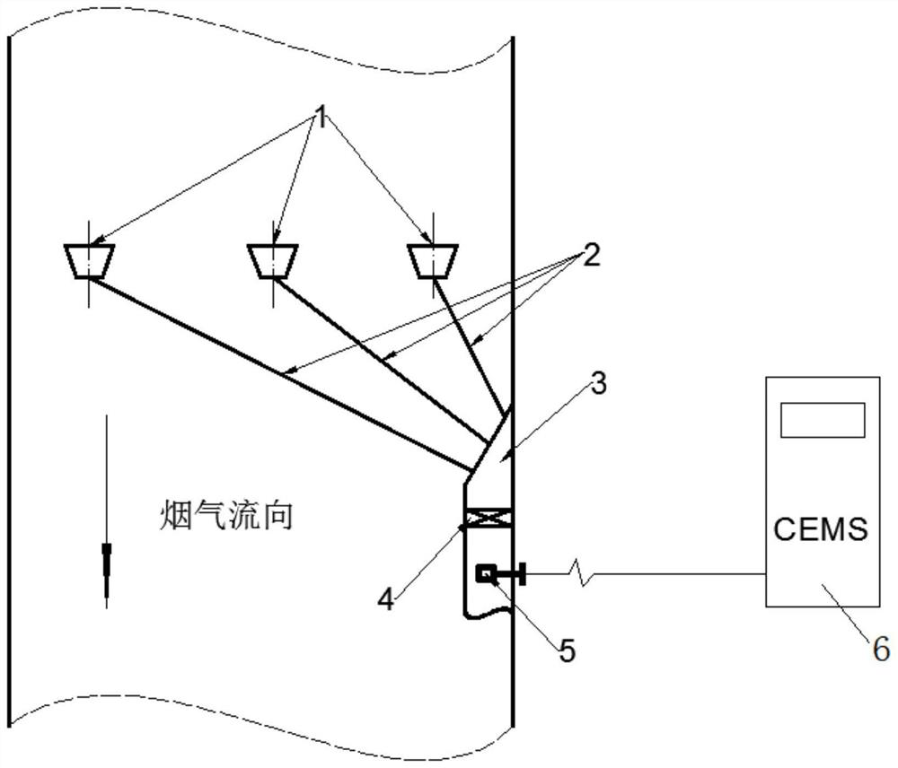
[0031] A boiler flue gas multi-point drainage mixing detection device of the present invention, such as figure 1 As shown, it includes a sampling system composed of a drainage chamber 1, a drainage tube 2, a manifold chamber 3 and a mixer 4, and a flue gas monitoring system composed of a CEMS probe 5 and a CEMS controller 6;

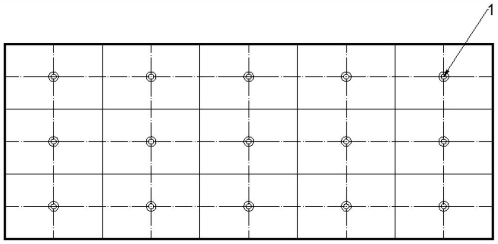
[0032] The drainage chamber 1 is a conical cylinder made of standard parts with different diameter joints, the central axis is consistent with the flow direction of the smoke, and the long diameter side section is the windward side, and the short diameter side is connected to the drainage pipe 2; several drainage chambers 1 adopt The grid method or the equal-area ring method is arranged on the flue section, such as figure 2 As shown, it is a schematic diagram of sever...


PUM


Abstract

The invention relates to a boiler flue gas component detection system, in particular to a boiler flue gas multi-point drainage mixing detection device. The system comprises a sampling system arranged in a flue and a flue gas monitoring system connected with the sampling system, the sampling system comprises a plurality of drainage cavities and drainage tubes, a confluence cavity and a mixer; the plurality of drainage cavities are arranged on the cross section of the flue by adopting a grid method or an equal-area circular ring method, and the plurality of drainage cavities are communicated with a confluence cavity in which a mixer is arranged through a plurality of drainage pipes which are connected with the plurality of drainage cavities in a one-to-one correspondence manner; the central axis of the drainage cavity is consistent with the flow direction of flue gas, the long-diameter side section of the drainage cavity is a windward side, and the short-diameter side of the drainage cavity is communicated with the drainage pipe; the confluence cavity is a cavity with the top and the periphery closed, is arranged on the inner wall plate of the flue and is communicated with the drainage pipe; and the detection end of the flue gas monitoring system is arranged in the drainage cavity and is positioned at the downstream of the outlet end of the mixer. The device is simple in principle, reliable in effect and easy to manufacture and install, and has good application and popularization value.

Description

technical field [0001] The invention relates to a boiler flue gas component detection system, in particular to a multi-point drainage and mixing detection device for boiler flue gas. Background technique [0002] The boiler system of a thermal power plant is complex and has a high degree of automation. The flue gas composition is an important basic parameter. The accuracy and representativeness of the detection results are crucial to the operation and control of the equipment. However, due to the huge boiler equipment, complex combustion conditions and many influencing factors, the flue gas component deviation on the flue section is often large. At present, the conventional flue gas adopts 1 to 2 probes per flue, and the length of the probe is about 1m. , for an ordinary 300MW coal-fired boiler, the flue cross section can usually reach 50m 2 Above, the flue section of 600MW and 1000MW units is larger. Therefore, conventional single-point detection probes often fail to obta...

Claims


Application Information

Patent Timeline
Patent Type & Authority Applications(China)
IPC IPC(8): G01N33/00G01N1/22G01N1/26G01N1/38
CPCG01N33/0004G01N1/2258G01N1/26G01N1/38
Inventor 李淑宏潘栋石磊尚桐杨世极舒凯徐晓涛
Owner XIAN THERMAL POWER RES INST CO LTD
Learn More