
A fixture for alleviating the uneven transition of the outer surface of the pipe-plug structure pressure resistance welding joint

A pressure resistance and welding head technology, which is applied in the field of clamps for relieving the uneven transition of the outer surface of the pressure resistance welding head of the pipe-plug structure, can solve the problems of easily damaged pipes, reduced joint performance, joint stress concentration, etc., and achieves increased fusion. Area, efficient manufacturing efficiency, the effect of realizing manufacturing efficiency

Active Publication Date: 2022-05-17
BEIJING UNIV OF TECH
View PDF0 Cites 0 Cited by
  • Summary
  • Abstract
  • Description
  • Claims
  • Application Information

AI Technical Summary

Problems solved by technology

The metal extruded into the pipe has the risk of crack initiation and expansion during service. However, the internal extruded metal is not easy to improve through clamping. Usually, the welding process is adjusted to avoid the appearance of internal extruded metal; The extruded metal will affect the smooth transition of the joint, causing problems such as stress concentration at the joint, resulting in a decrease in the performance of the joint. Generally, the external extruded metal needs to be polished and smoothed by mechanical means after welding. However, other parts are easy to be damaged during the grinding process. pipe

Method used

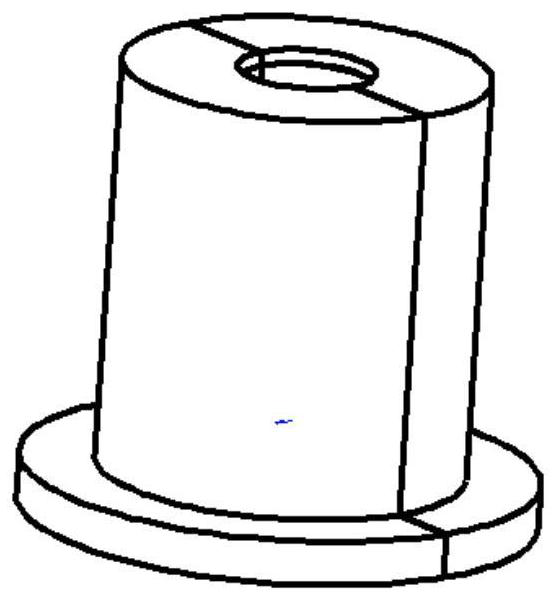
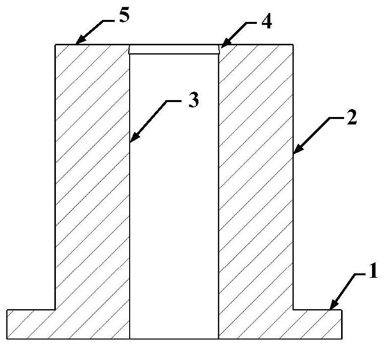
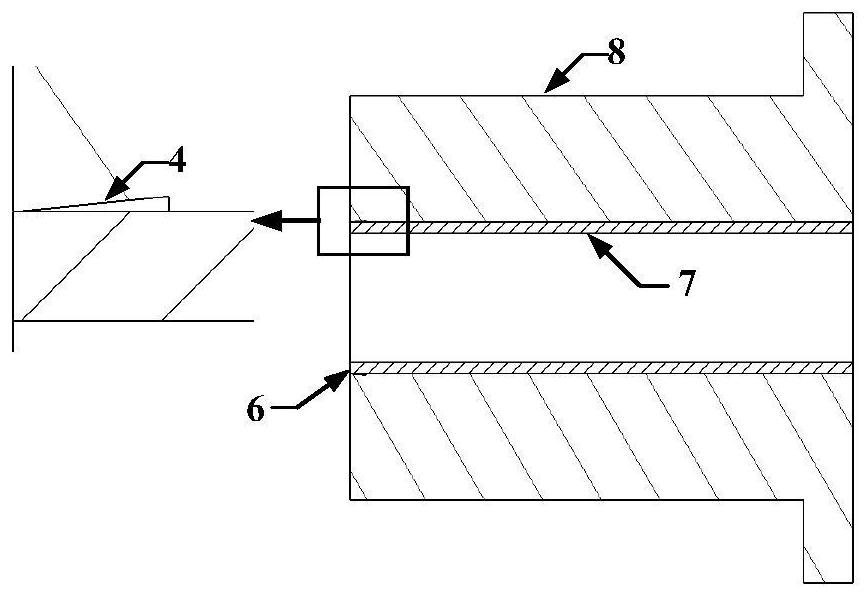

Image

  • A fixture for alleviating the uneven transition of the outer surface of the pipe-plug structure pressure resistance welding joint
  • A fixture for alleviating the uneven transition of the outer surface of the pipe-plug structure pressure resistance welding joint
  • A fixture for alleviating the uneven transition of the outer surface of the pipe-plug structure pressure resistance welding joint

Examples


Embodiment 1

[0026] In this embodiment, pressure resistance welding is performed on the Zr-4 end plug and the CZ pipe on the Gleeble thermal simulator, and the specific steps are as follows:

[0027] 1. Before pressure resistance welding, use #1500 sandpaper to lightly grind the welding end face (6) of the cladding tube, so as to ensure full contact between the cladding tube and the end plug, and prevent the joint from burning due to poor contact. Use absorbent cotton dipped in acetone solution to wipe the oil and impurities on the surface of the workpiece.

[0028] 2. Clamp the end plug and the pipe respectively inside the corresponding clamps. The pipe is clamped by the clamp (8) with the oblique line segment hole wall. The clamping schematic diagram is as follows image 3 . After the clamping is completed, the hydraulic device is used to push the fixture on the side of the end plug to form a butt joint between the end plug and the pipe, and finally vacuumize.

[0029] 3. Set the press...


PUM


Abstract

A clamp for relieving the uneven transition of the outer surface of a pressure resistance welded joint of a pipe-plug structure belongs to the technical field of clamps. It is designed to alleviate the problem of uneven transition of the outer surface of the joint during the pressure resistance welding process. The fixture is a center-symmetrical structure and consists of two parts. The first part is a base, which can cooperate with the positioning fixture of the welding equipment to play a positioning role; the second part is a hollow cylinder of the fixture, and the front end of the cylinder is The end faces of the pipes to be welded are flush, and the inner wall includes a straight section hole wall and an oblique section hole wall. The hole wall of the straight section matches the outer diameter of the pipe to be welded, and the hole wall of the oblique section can limit the free flow of the extruded metal under the action of high temperature and pressure during the welding process, and finally make the extruded metal flow radially along a certain angle, and The interface is combined with the end plug, which greatly alleviates the problem of uneven transition on the outer surface of the joint, and can also increase the fusion area of ​​the pressure resistance welding and improve the mechanical properties of the joint.

Description

technical field [0001] The invention belongs to the technical field of fixtures, in particular to a fixture for alleviating the uneven transition of the outer surface of a pressure resistance welding joint of a pipe-plug structure. Background technique [0002] In pressure resistance welding, the pipe and the end plug are clamped in two pairs of fixtures with similar sizes, and the end face of the pipe is generally kept parallel to the end face of the fixture, that is, the pipe does not protrude out of the fixture. After the welding process starts, the joint action of the welding current and the pipe-plug interface resistance produces a large heat source, and under the upsetting of the welding pressure, the pipe will extrude part of the metal to the inside and outside. The metal extruded into the pipe has the risk of crack initiation and expansion during service. However, the internal extruded metal is not easy to improve through clamping. Usually, the welding process is adj...

Claims


Application Information

Patent Timeline
Patent Type & Authority Patents(China)
IPC IPC(8): B23K11/36B23K11/00B23K37/053B23K101/06
CPCB23K11/36B23K11/00B23K37/053B23K2101/06
Inventor 林健冯刚雷永平符寒光季顺成崔泰然杨乐
Owner BEIJING UNIV OF TECH
Learn More