Plate shearing machine

A technology of shearing machine and machine body, which is applied in the field of steel plate processing, can solve the problems of low processing efficiency, achieve the effects of improving processing efficiency, convenient operation, and increasing versatility

Active Publication Date: 2021-09-24
XIANGYANG XINJINKAI PUMP CO LTD
View PDF8 Cites 2 Cited by
  • Summary
  • Abstract
  • Description
  • Claims
  • Application Information

AI Technical Summary

Problems solved by technology

[0004] The purpose of the present invention is to provide a plate shearing machine, aiming to solve the problem of low processing efficiency caused by manually pushing steel plates for shearing

Method used


Image

  • Plate shearing machine
  • Plate shearing machine
  • Plate shearing machine

Examples


Embodiment Construction

[0032] The technical solution of the present invention will be clearly and completely described below in conjunction with the accompanying drawings and specific embodiments. Apparently, the described embodiments are only some of the embodiments of the present invention, not all of them. Based on the embodiments of the present invention, all other embodiments obtained by persons of ordinary skill in the art without creative efforts fall within the protection scope of the present invention.

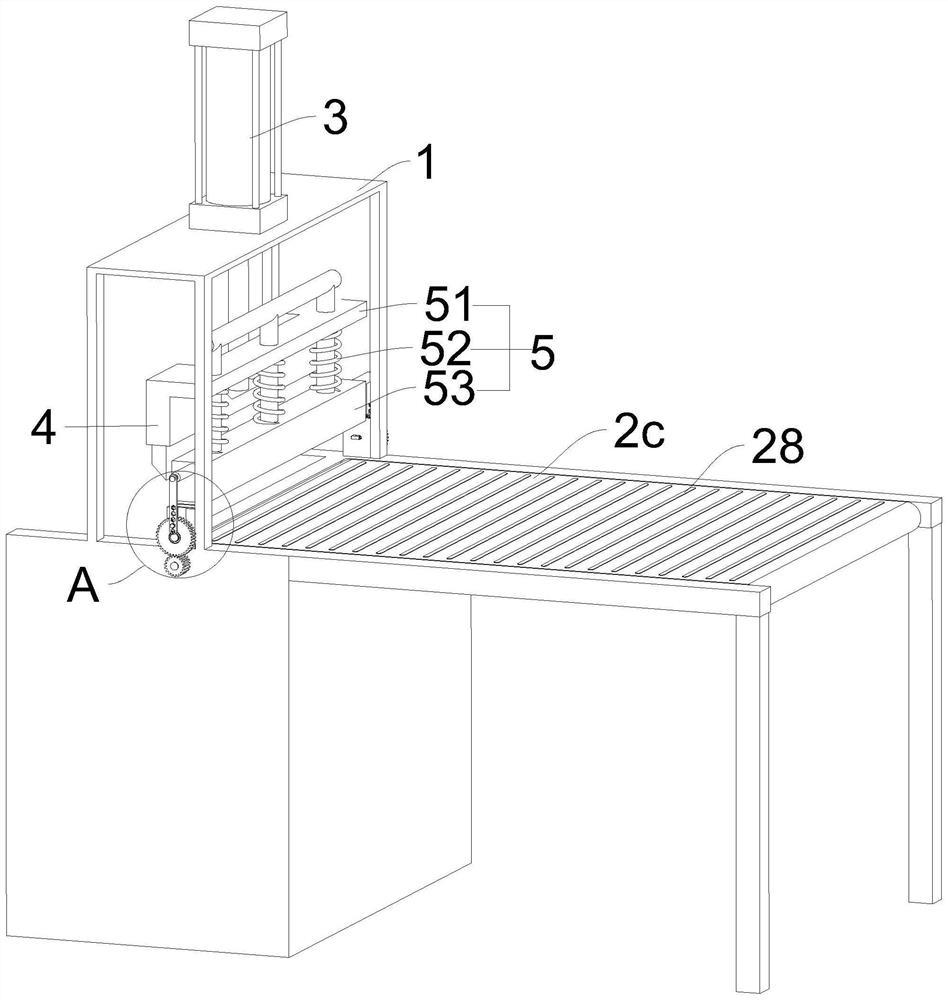
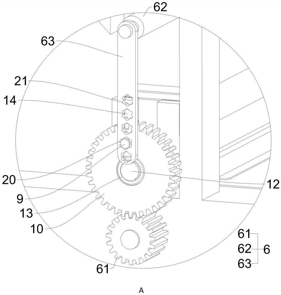
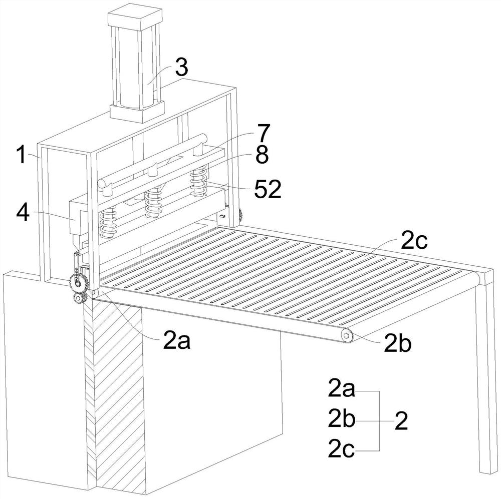
[0033] A kind of shearing machine provided by the invention, such as Figure 1 to Figure 5 As shown, it includes a body 1, a feeding mechanism 2 arranged on the body 1, a driving cylinder 3 arranged on the top of the body 1, and a shearing member 4 arranged at the output end of the driving cylinder 3 along the vertical direction, and a part of the shearing member 4 The side is provided with a fixing mechanism 5 for fixing the steel plate, and the shearing member 4 can drive the fixing mech...


PUM


Abstract

The invention relates to the field of steel plate machining, and discloses a plate shearing machine which comprises a machine body, a feeding mechanism arranged on the machine body, a driving air cylinder arranged at the top of the machine body and a shearing piece arranged at the output end of the driving air cylinder in the vertical direction. A fixing mechanism for fixing a steel plate is arranged on one side of the shearing piece, the driving air cylinder can drive the fixing mechanism to move up and down in a reciprocating mode through the shearing piece, and driving mechanisms used for pushing the feeding mechanism to move in the direction close to the shearing piece are symmetrically arranged on the two sides of the fixing mechanism. In the process that the fixing mechanism drives the driving mechanism to move up and down in a reciprocating mode, the driving mechanism drives a feeding mechanism to push the steel plate forwards, the steel plate does not need to be pushed forwards manually in cooperation with movement of the shearing piece, and therefore the purpose of improving the machining efficiency is achieved.

Description

technical field [0001] The invention relates to the technical field of steel plate processing, in particular to a shearing machine. Background technique [0002] The plate shearing machine is a machine that uses one blade to make a reciprocating linear motion relative to the other blade to cut the plate. It uses the moving upper blade and the fixed lower blade to apply shear to metal plates of various thicknesses with a reasonable blade gap. Force, so that the plate is broken and separated according to the required size. [0003] However, when using the shearing machine to continuously shear the steel plate, it is necessary to manually cooperate with the shearing machine to push the steel plate forward, resulting in low processing efficiency. Contents of the invention [0004] The object of the present invention is to provide a plate shearing machine, aiming to solve the problem of low processing efficiency caused by manually pushing steel plates for shearing. [0005] T...

Claims


Application Information

Patent Timeline
IPC IPC(8): B23D15/08B23D33/02B23D33/08
CPCB23D15/08B23D33/02B23D33/08
Inventor 刘亚娟
Owner XIANGYANG XINJINKAI PUMP CO LTD
Why Eureka
Try Eureka