
Bonding structure, bonding method and display device

A bonding and layered structure technology, applied in the direction of instruments, semiconductor devices, optics, etc., can solve problems such as unevenness, unsatisfactory broken conductive particles, poor bonding, etc.

Active Publication Date: 2021-09-21
HEFEI VISIONOX TECH CO LTD
View PDF9 Cites 0 Cited by
  • Summary
  • Abstract
  • Description
  • Claims
  • Application Information

AI Technical Summary

Problems solved by technology

[0003] However, bad bonding has always been one of the bad things that show a high incidence in the industry
The unsatisfactory or uneven breakage of ACF conductive

Method used


Image

  • Bonding structure, bonding method and display device
  • Bonding structure, bonding method and display device
  • Bonding structure, bonding method and display device

Examples


Embodiment Construction

[0043] In order to facilitate the understanding of the present application, the present application will be described more fully below with reference to the relevant drawings. Preferred embodiments of the application are shown in the accompanying drawings. However, the present application can be embodied in many different forms and is not limited to the embodiments described herein. On the contrary, the purpose of providing these embodiments is to make the understanding of the disclosure of the present application more thorough and comprehensive.

[0044] Unless otherwise defined, all technical and scientific terms used herein have the same meaning as commonly understood by one of ordinary skill in the technical field to which this application belongs. The terms used herein in the specification of the application are only for the purpose of describing specific embodiments, and are not intended to limit the application.

[0045]It should be noted that when an element is refer...


PUM


Abstract

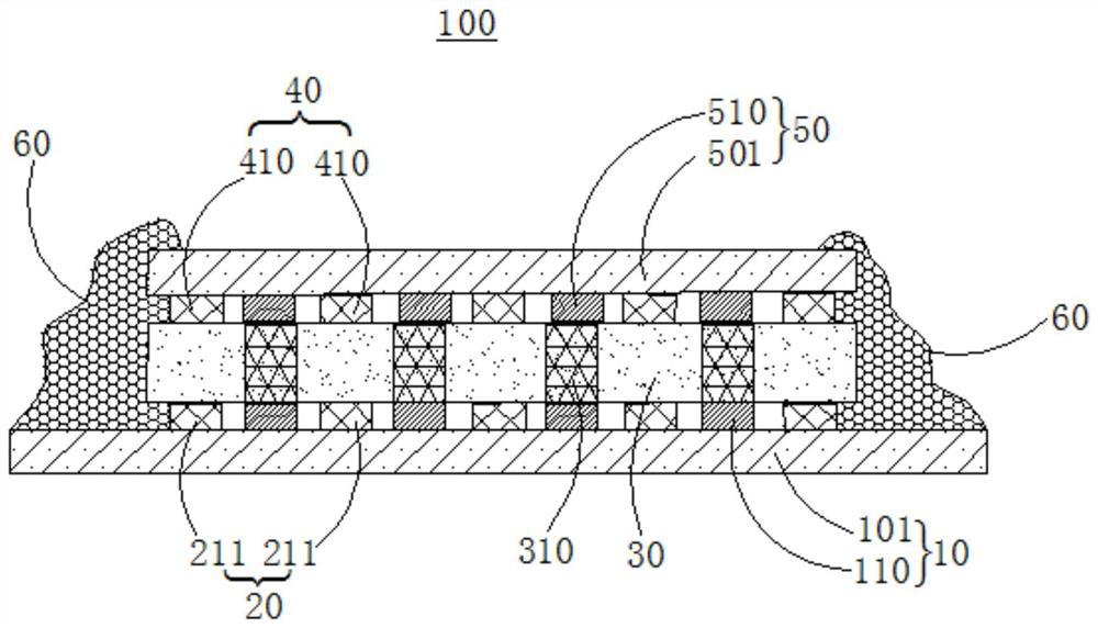
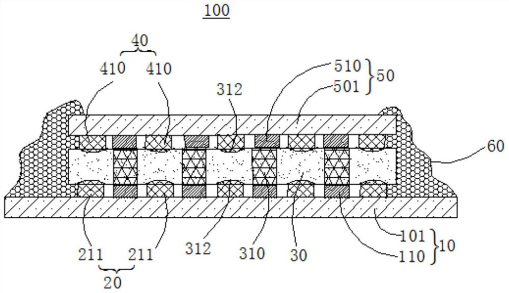
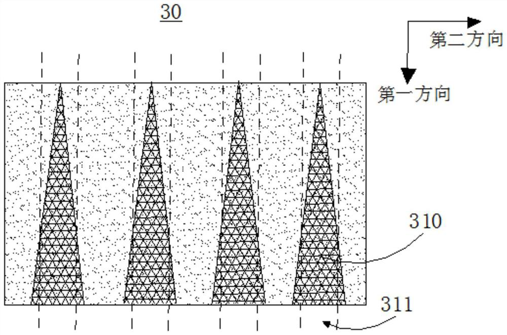
The invention relates to a bonding structure, a bonding method and a display device. The bonding structure comprises a first circuit board, a second circuit board and a photoinduced variable resistance layer. The first circuit board comprises a first substrate and a plurality of first electrodes arranged on the first substrate at intervals. The second circuit board comprises a second substrate and a plurality of second electrodes arranged on the second substrate at intervals. One first electrode is opposite to one second electrode; and the photoinduced variable resistance layer is clamped between the first circuit board and the second circuit board. The plurality of first electrodes and the plurality of second electrodes are respectively in contact with two opposite surfaces of the photoinduced variable resistance layer. After the photochromic resistance changing layer is illuminated, the resistivity is reduced and the photochromic resistance changing layer is conductive. A plurality of conductive regions arranged at intervals are arranged in the photoinduced variable resistance layer. One conductive region corresponds to one first electrode and one second electrode, and one first electrode is electrically connected with one second electrode. The bonding structure can realize longitudinal conduction of the upper-layer electrode and the lower-layer electrode, and enables the plurality of electrodes to be transversely insulated.

Description

technical field [0001] The present application relates to the field of display technology, in particular to a bonding structure, a bonding method and a display device. Background technique [0002] As the upgrading of electronic equipment accelerates, the requirements for integration and performance of display devices are getting higher and higher, and it is particularly important to detect abnormalities in the production process of display devices in time. The bonding method can be applied to structures requiring bonding, such as flexible printed circuit (FPC), chip on flex (COF), and panels. The bonding process of flexible circuit board bonding on the panel (FPC onpanel, FOP) or flexible circuit board bonding on the chip-on-film (FPC of COF, FOF) includes anisotropic conductive film (anisotropic conductive film, ACF) pre-attachment, pre-compression , pressure and detection. [0003] However, bad bonding has always been one of the most frequent defects in the display indu...

Claims


Application Information

Patent Timeline
IPC IPC(8): G02F1/1333H01L51/52
CPCG02F1/133308G02F1/1333H10K50/84
Inventor 赵文许立雄于振坤韩乐乐吴国东
Owner HEFEI VISIONOX TECH CO LTD
Learn More