
Anodic bonding equipment

An anodic bonding and equipment technology, which is applied in the fields of electrical components, semiconductor/solid-state device manufacturing, circuits, etc., can solve the problems that affect the normal use of silicon wafers and glass wafers, the sealing surface is not tightly bonded, and the output is low.

Active Publication Date: 2021-07-13
PUTIAN UNIV
View PDF9 Cites 0 Cited by
  • Summary
  • Abstract
  • Description
  • Claims
  • Application Information

AI Technical Summary

Problems solved by technology

[0004] The purpose of the present invention is: in order to solve the problem that there may still be some fine particle impurities such as dust on the surface of the silicon wafer and the glass wafer. In the normal use of sheets and glass sheets, a heating mechanism is generally required during bonding, but the heating mechanism is in a high temp

Method used


Image

  • Anodic bonding equipment
  • Anodic bonding equipment
  • Anodic bonding equipment

Examples


Example Embodiment

[0037]Next, the technical solutions in the embodiments of the present invention will be apparent from the embodiment of the present invention, and it is clearly described, and it is understood that the described embodiments are merely embodiments of the present invention, not all of the embodiments. Based on the embodiments in the present invention, those of ordinary skill in the art will belong to the scope of the present invention in the scope of the present invention without any other embodiments obtained without creative labor.

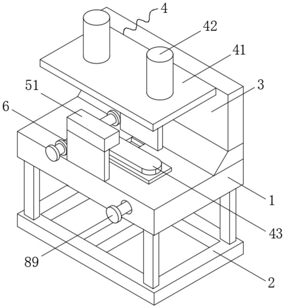
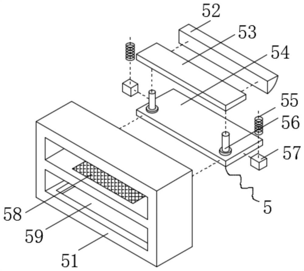
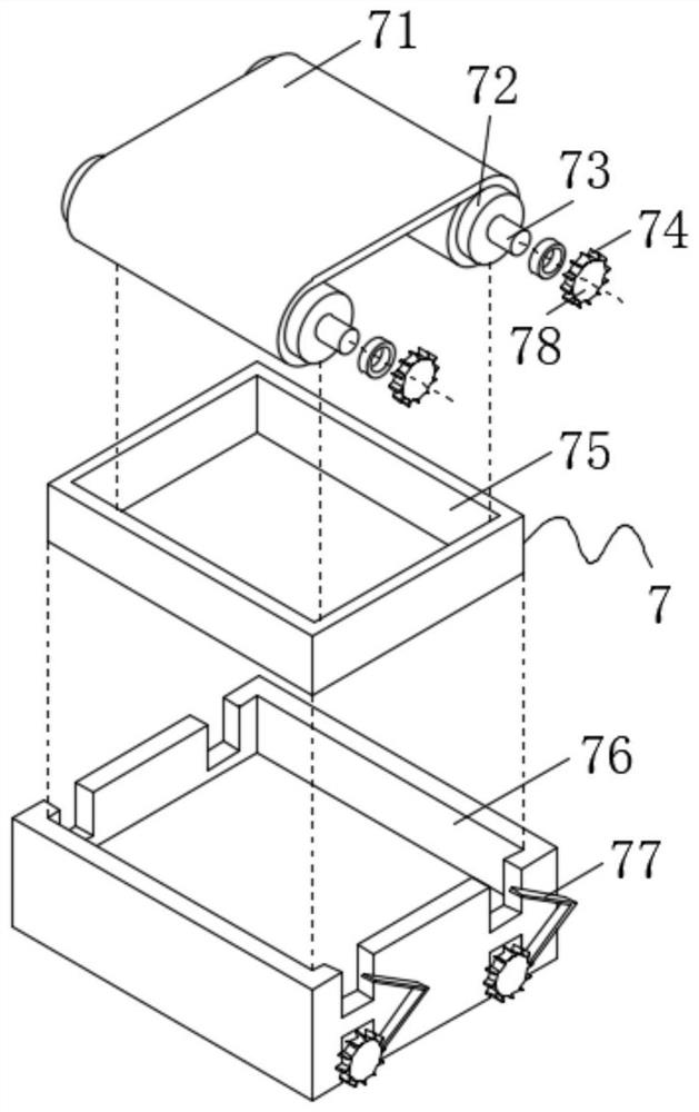
[0038] See Figure 1-6 The present invention provides a technical solution: an anode bonding apparatus comprising a base 1, a bracket 2, and a side plate 3 having a side plate 3 and a stent 2, a side plate 3, respectively, a side plate 3, respectively. A bonding mechanism 4 is provided on the front, and the front and rear sides of the bonding mechanism 4 are provided with a clamping mechanism 5 and a dust collecting mechanism 7, a lower surface of the ...


PUM


Abstract

The invention discloses anodic bonding equipment, and belongs to the technical field of anodic bonding, the anodic bonding equipment comprises a base, a support and a side plate, the side plate and the support are fixedly connected to the upper side face and the lower side face of the base respectively, a bonding mechanism is arranged on the front face of the side plate, and a clamping mechanism and a dust cleaning mechanism are arranged on the front side and the rear side of the bonding mechanism respectively. And mounting plates are fixedly connected to the lower surfaces of the clamping mechanism and the dust cleaning mechanism. According to the invention, the clamping mechanism is arranged, a silicon wafer and a glass sheet can be placed in a through hole, and an electromagnet plate can generate a repulsion effect on magnetic supporting plates when being electrified, so that the two supporting plates are far away from each other and are matched with the inner wall of a first fixing block to effectively position the silicon wafer and the glass sheet; and meanwhile, the first connecting plate is driven to move through the connecting rod, the arc-shaped plate generates an extrusion effect on the silicon wafer or the glass sheet, the silicon wafer and the glass sheet are extruded out, the silicon wafer and the glass sheet are attached together, and the rapid assembly effect is achieved.

Description

technical field [0001] The invention belongs to the technical field of anodic bonding, and in particular relates to anodic bonding equipment. Background technique [0002] Anodic bonding is a method of wafer bonding widely used in the microelectronics industry that uses a combination of heat and an electrostatic field to seal two surfaces together. This bonding technique is most commonly used to seal glass layers onto silicon wafers. [0003] When the bonding equipment bonds the silicon wafer to the glass wafer, there may still be some fine particle impurities such as dust on the surface of the silicon wafer and the glass wafer. These impurities will affect the bonding effect of the silicon wafer and the glass wafer, resulting in poor bonding of the sealing surface. Compactness affects the normal use of silicon wafers and glass sheets. At the same time, a heating mechanism is generally used during bonding, but the heating mechanism is in a high temperature state when used f...

Claims


Application Information

Patent Timeline
IPC IPC(8): H01L21/67
CPCH01L21/67126
Inventor 郑志霞何灏泽黄赛琴
Owner PUTIAN UNIV
Learn More