Microwave sensor detection circuit for multiple detection scenes and design method thereof

A microwave sensor and detection circuit technology, applied in the direction of transmitting sensing components by wave/particle radiation devices, can solve the problems of unsuitable resonator-type microwave sensor detection, large phase noise, high hardware cost, etc., and achieve excellent insertion loss resolution Rate and linearity, large optional frequency space, and enhanced anti-interference ability

Active Publication Date: 2021-09-17
JIANGNAN UNIV
View PDF10 Cites 1 Cited by
  • Summary
  • Abstract
  • Description
  • Claims
  • Application Information

AI Technical Summary

Problems solved by technology

But there are still the following disadvantages: complex circuit structure and high hardware cost; in addition, the biggest problem is that this system is not suitable for the detection of resonator-type microwave sensors, and this system is suitable for discrete antennas as moisture sensing elements
[0006] In 2018, Sichuan Feixun Information Technology Co., Ltd. published the invention patent "A Method and System for Testing Insertion Loss", the publication number is: CN108646097A. Although the detection of microwave sensors in this patent is also based on insertion loss, on the one hand, its microwave source is Ordinary waveform generation modules have high RF output phase noise and are not suitable for high-precision detection. Secondly, the patent does not provide a universal detection circuit model, and its application has limitations.
[0007] In 2020, the University of Electronic Science and Technology of China published the invention patent "A Scattering Matrix Parameter Detection System for Microwave Sensing", the publication number is: CN112097815A. Although the system structure proposed in this patent can realize the detection of microwave sensors, its essence is still The principle of vector network analyzer is applied, and the detection of resonance point by local oscillator frequency sweep will make its circuit structure extremely complicated, and an additional controller is required to control the frequency divider of the phase-locked loop
In addition, because the fast switching of the frequency divider will bring great phase noise, how to suppress the phase noise is also a very complicated process

Method used


Image

  • Microwave sensor detection circuit for multiple detection scenes and design method thereof
  • Microwave sensor detection circuit for multiple detection scenes and design method thereof
  • Microwave sensor detection circuit for multiple detection scenes and design method thereof

Examples


Embodiment Construction

[0037] The present invention will be further described below in conjunction with the accompanying drawings and specific embodiments, so that those skilled in the art can better understand the present invention and implement it, but the examples given are not intended to limit the present invention.

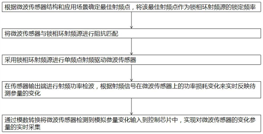
[0038] refer to figure 1 As shown, a method for designing a microwave sensor detection circuit facing multiple detection scenarios of the present invention: comprises the following steps:

[0039] S1. Determine the best radio frequency point according to the microwave sensor structure and application scenarios, and use the best radio frequency point as the locking frequency of the phase-locked loop radio frequency source;

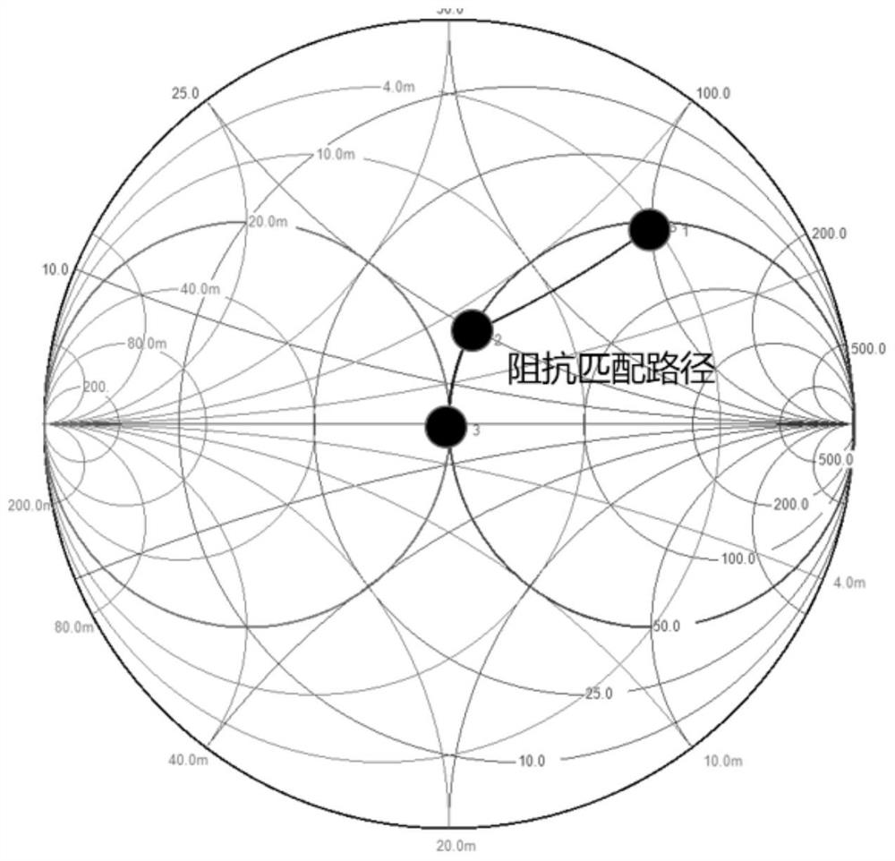
[0040] S2. Impedance matching is performed between the microwave sensor and the phase-locked loop radio frequency source;

[0041] S3. Use a phase-locked loop RF source to drive a microwave sensor with a single-frequency point RF;

[0042] S4. Carry out radio f...


PUM


Abstract

The invention relates to a microwave sensor detection circuit for multiple detection scenes and a design method thereof. The design method comprises the following steps of S1, determining an optimal radio frequency point according to a microwave sensor structure and an application scene, and taking the optimal radio frequency point as a locking frequency of a phase-locked loop radio frequency source, S2, performing impedance matching on the microwave sensor and a phase-locked loop radio frequency source, S3, performing single-frequency-point radio frequency driving on the microwave sensor by adopting a phase-locked loop radio frequency source, S4, performing radio frequency power detection at the output end of the sensor, and reflecting the change of the to-be-measured parameter in real time according to the power loss change of the radio frequency signal on the microwave sensor, and S5, inputting analog parameter changes detected by the microwave sensor into the control chip through analog-to-digital conversion, and realizing real-time collection of change parameters of the microwave sensor. The invention provides a miniaturized, low-cost, low-power-consumption and high-precision detection circuit and a design method thereof.

Description

technical field [0001] The present invention relates to the technical field of microwave sensor detection, in particular to a microwave sensor detection circuit for multiple detection scenarios and a design method thereof. Background technique [0002] With the advent of the Internet of Things era, my country's demand for high-precision, high-sensitivity, fast-response, and high-reliability networked smart sensors is increasing day by day. As a new type of high-performance sensor, the microwave sensor can be applied to a variety of harsh detection scenarios. For example, as a non-contact non-destructive detection method, microwave humidity sensor can be used in cement, granary and wood and other application scenarios that require strict humidity sensor; and various biological sensors using microwave technology, such as blood sugar microwave sensor, cancer cell Microwave sensors, etc. are shining in the field of non-invasive biological detection. In addition, microwave sens...

Claims


Application Information

Patent Timeline
Patent Type & Authority Applications(China)
IPC IPC(8): G01D5/48
CPCG01D5/48
Inventor 梁峻阁付晓东王琮顾晓峰
Owner JIANGNAN UNIV
Why Eureka
Try Eureka