Medium-fine-particle graphite product hot-press forming device capable of improving compactness of paste
A hot-press forming and compaction technology, applied in the material forming press, graphite, press and other directions, can solve the problem of poor compactness, and achieve the effect of improving compactness, reducing mold deformation, and stabilizing hot-pressing without shaking.
- Summary
- Abstract
- Description
- Claims
- Application Information
AI Technical Summary
Problems solved by technology
Method used
Image
Examples
Embodiment 1
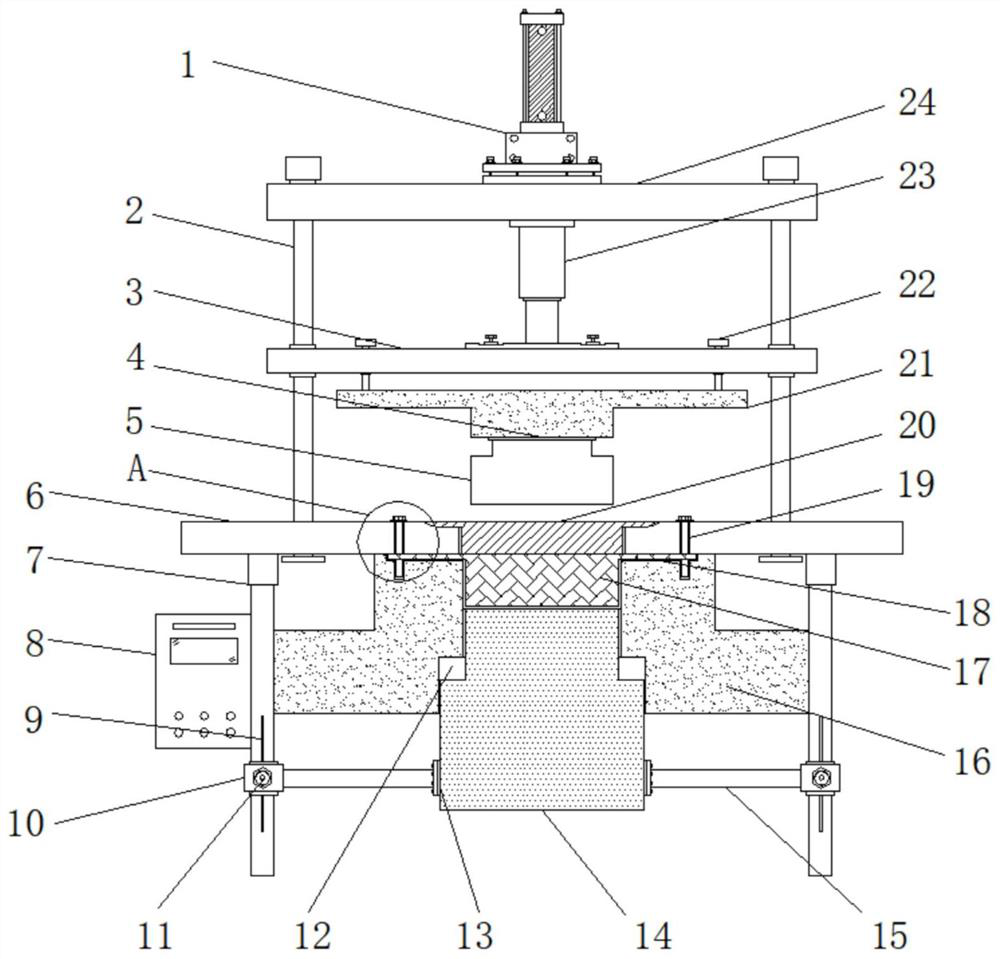
[0021] Example 1: See Figure 1-4 , a kind of hot-press molding device for medium and fine particle graphite products that can improve the compactness of the paste, including a processing table 6 and a gantry 2, the top of the processing table 6 is equipped with a gantry 2, the top of the gantry 2 is riveted with a top plate 24, and the gantry The outside of frame 2 is sleeved with movable plate 3, and the top of top plate 24 is fixedly connected with cylinder 1, and the output end of cylinder 1 is provided with piston rod 23, and piston rod 23 runs through the inside of top plate 24 and extends to the bottom of top plate 24, and the piston rod The bottom end of 23 is fixedly connected with the top of the moving plate 3 by a steel sheet, the bottom end of the moving plate 3 is provided with an upper mold base 21, the two sides of the bottom end of the processing table 6 are equipped with supporting feet 7, and one side of the supporting feet 7 is equipped with a controller 8. ...
Embodiment 2
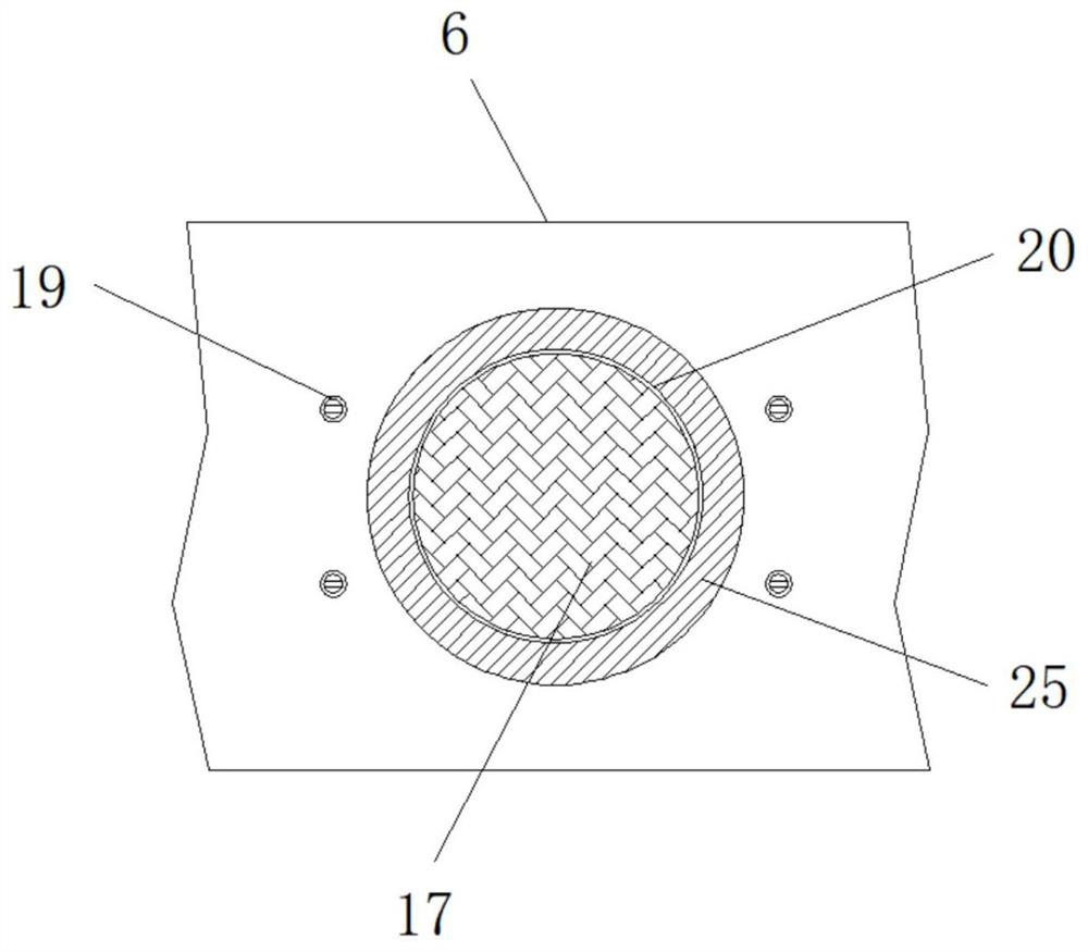
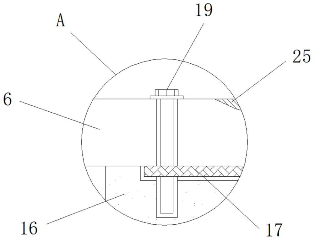
[0024] Embodiment 2: The upper cavity 18 is set on the top of the lower mold base 16, and the middle position inside the processing table 6 is provided with a pressure groove 20. The upper cavity 18 and the pressure groove 20 are vertically aligned, and the top of the pressure groove 20 The edge of the edge is provided with an overflow edge groove 25, and the overflow edge groove 25 is annular, and the inside of the upper cavity 18 is equipped with a mold 17, and a positioning bolt 19 is fixedly connected between the mold 17, the lower mold base 16 and the processing table 6, and the positioning bolt 19 There are four groups, and the shapes of the mold 17 and the upper cavity 18 match;
[0025] Specifically, as figure 1 , figure 2 and image 3 As shown, the mold 17, the upper mold cavity 18 and the processing table 6 are tightly fixed by four sets of positioning bolts 19, the mold 17 is firmly installed inside the upper mold cavity 18, and the outer wall is closely attached...
Embodiment 3
[0026] Embodiment 3: The lower die cavity 12 is provided at the bottom end inside the lower mold base 16, and the inside of the lower die cavity 12 is embedded with a press table 14, and the bottom ends on both sides of the press table 14 are fixedly connected with fixed rods 15, and the fixed rods 15 and the press A connecting flange 13 is installed between the platforms 14, an adjusting sleeve 10 is welded on the side of the fixed rod 15 away from the pressing table 14, and the adjusting sleeve 10 is sleeved on the outside of the leg 7, and the inside of the leg 7 is provided with an adjusting groove 9, and the adjusting groove A locking bolt 11 is fixedly connected between the 9 and the adjusting sleeve 10;
[0027] The shape of the lower cavity 12 matches the press table 14, and the cross section of the lower cavity 12 and the press table 14 is "convex";
[0028] Specifically, as figure 1 , figure 2 , image 3 and Figure 4 As shown, affected by the long-term hot pres...
PUM
 Abstract
Description
Claims
Application Information
 - R&D
- Intellectual Property
- Life Sciences
- Materials
- Tech Scout
- Unparalleled Data Quality
- Higher Quality Content
- 60% Fewer Hallucinations
Browse by: Latest US Patents, China's latest patents, Technical Efficacy Thesaurus, Application Domain, Technology Topic, Popular Technical Reports.
© 2025 PatSnap. All rights reserved.Legal|Privacy policy|Modern Slavery Act Transparency Statement|Sitemap|About US| Contact US: help@patsnap.com


