
A stainless steel material processing equipment capable of rapid cooling

A material processing, stainless steel technology, applied in the field of stainless steel material processing equipment, can solve the problems of cost increase, bloated equipment, energy usage, etc., and achieve the effect of improving processing efficiency, increasing effect and efficiency, and improving automation

Active Publication Date: 2022-02-18
JIANGSU XINGHAI SPECIAL STEEL
View PDF13 Cites 0 Cited by
  • Summary
  • Abstract
  • Description
  • Claims
  • Application Information

AI Technical Summary

Problems solved by technology

[0003] The existing patent No. CN103522134B proposes a grinding machine for the inner wall of an aluminum bottle, including a frame, a grinding shaft and a motor. The left side of the frame is provided with a vertical guide rail, and a platform is provided on the guide rail; The motor includes a first motor and a second motor, the first motor is arranged on the platform, the lower edge of the platform is connected to a cylinder, and the cylinder is arranged under the platform and fixed on the frame On the left side; one side below the grinding shaft is provided with a rotating shaft, and the other side below the grinding shaft is provided with a rotating wheel set, and the rotating shaft and the rotating wheel set are arranged in the frame. Automated equipment partially replaces manual operations, reduces the labor intensity of workers, and improves production efficiency, but it lacks cooling methods for stainless steel materials. After grinding stainless steel materials, in order to improve subsequent processing efficiency, stainless steel materials need to be cooled. However, the above-mentioned equipment requires an additional cooling mechanism to cool the stainless steel material. The use of the cooling mechanism will lead to increased costs, energy use, bloated devices, and low efficiency, which is not conducive to energy conservation, environmental protection, and efficiency improvement.
[0004] The existing patent No. CN107081644B proposes a pipe fitting inner wall grinding device, including a base, a first push rod motor is installed on one side of the top of the base, a first slider is installed on the output shaft of the first push rod motor, and a The first chute, the first slider is slidably installed in the first chute, and the first slider extends to the outside of the first chute, and the end of the first slider located outside the first chute is fixed with a first servo Motor, the output shaft of the first servo motor is equipped with a turntable, and the first servo motor is installed at the center of one end of the turntable, and the end of the turntable away from the output shaft of the first servo motor is provided with a second chute, the second A number of screw holes are provided in the chute, and two first fixing seats are slidingly provided in the second chute, and the two first fixing seats are symmetrically installed in the second chute, and the four corners of the two first fixing seats are provided with There are fixing bolts, and the fixing bolts are matched with the screw holes, the second servo motors are installed in the center of the two first fixing seats, the output shafts of the two second servo motors are equipped with hollow rods, and the hollow rods are far away from the second servo motor. A telescopic rod is installed in one end of the output shaft of the motor, and the telescopic rod extends to the outside of the hollow rod. The second fixed seat is installed on the end of the telescopic rod outside the hollow rod, which can control the grinding of the grinding head more accurately and make the grinding accuracy more accurate. At the same time, the clamping block is set to be adjustable so that the present invention can be applied to pipe fittings of various diameters, but the function is single, and only has the function of grinding stainless steel materials, and also cannot meet the above-mentioned heat dissipation requirements for stainless steel materials

Method used


Image

  • A stainless steel material processing equipment capable of rapid cooling
  • A stainless steel material processing equipment capable of rapid cooling
  • A stainless steel material processing equipment capable of rapid cooling

Examples


Embodiment Construction

[0031] The following will clearly and completely describe the technical solutions in the embodiments of the present invention with reference to the accompanying drawings in the embodiments of the present invention. Obviously, the described embodiments are only some, not all, embodiments of the present invention. Based on the embodiments of the present invention, all other embodiments obtained by persons of ordinary skill in the art without making creative efforts belong to the protection scope of the present invention.

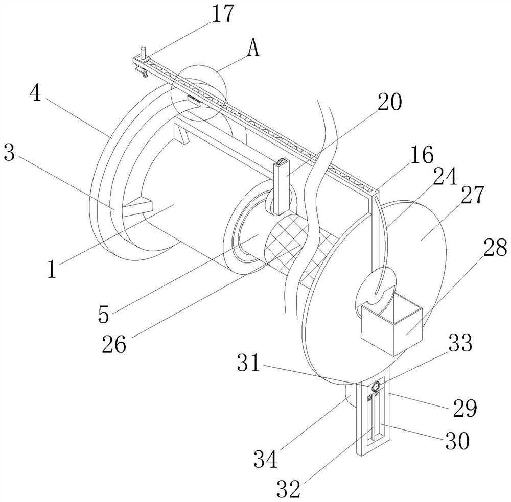
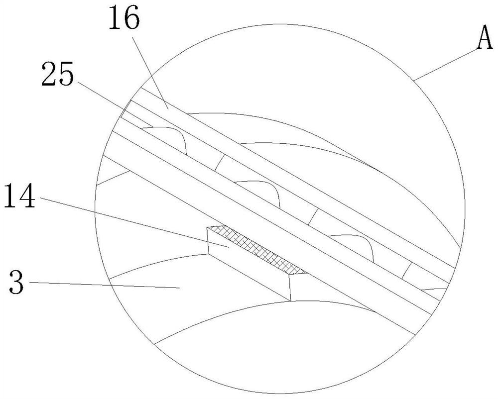
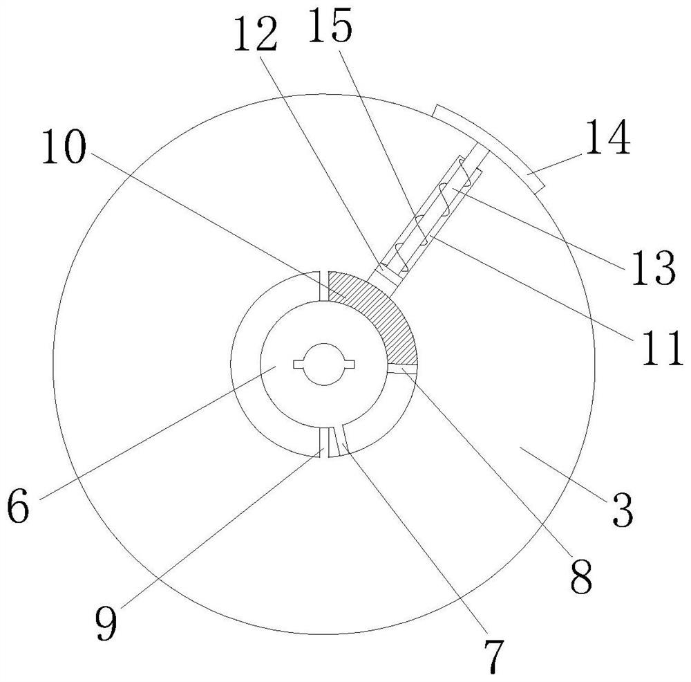
[0032] see Figure 1-7, a stainless steel material processing equipment capable of rapid cooling, including a heat insulation cylinder 1 with a hollow back and heat insulation material, the inner wall of the heat insulation cylinder 1 is provided with a rectangular protrusion and is fixedly connected with a rotating motor 2, and the transmission of the rotating motor 2 A sleeve shaft 6 is fixedly installed on the shaft, and the outer wall of the sleeve shaft 6...


PUM


Abstract

The invention relates to the technical field of stainless steel processing, and discloses a stainless steel material processing equipment that can quickly cool down, including a heat insulation cylinder, the inner wall of the heat insulation cylinder is provided with a rectangular protrusion and is fixedly connected with a rotating motor, and the transmission shaft of the rotating motor is fixed. The sleeve shaft is installed, the outside of the sleeve shaft is inserted into a sleeve, the back of the sleeve is fixedly installed with a grinding plate, the inner upper right side of the sleeve is provided with a telescopic groove, the inner wall of the telescopic groove is sleeved with a piston, and the top surface of the piston is fixedly connected with a The stopper rod is fixedly connected with a pressing block. Through the setting of the pressing block, the device can switch its function according to the different rotation directions of the rotating motor drive shaft, so that the device has the function of grinding the inner wall of the tubular stainless steel material, and solves the problem of tubular stainless steel. The difficulty of grinding the inner wall of the material also enables the device to have the function of driving the tubular stainless steel material to rotate together for rapid cooling, which improves the processing efficiency and the convenience of the device, and avoids the cost increase caused by the installation of an additional cooling mechanism.

Description

technical field [0001] The invention relates to the technical field of stainless steel processing, in particular to a stainless steel material processing equipment capable of rapidly cooling down. Background technique [0002] Stainless steel materials need to be polished and polished before production, and the processing of tubular stainless steel materials is special, and the inner wall needs to be polished and polished. It is necessary to use grinding equipment to work deep into the inner wall of stainless steel materials. [0003] The existing patent No. CN103522134B proposes a grinding machine for the inner wall of an aluminum bottle, including a frame, a grinding shaft and a motor. The left side of the frame is provided with a vertical guide rail, and a platform is provided on the guide rail; The motor includes a first motor and a second motor, the first motor is arranged on the platform, the lower edge of the platform is connected to a cylinder, and the cylinder is ar...

Claims


Application Information

Patent Timeline
Patent Type & Authority Patents(China)
IPC IPC(8): B24B5/35B24B5/40B24B41/04B24B41/06B24B47/12B24B47/20B24B47/22B24B55/02
CPCB24B5/40B24B5/35B24B41/04B24B47/22B24B55/02B24B41/06B24B47/12B24B47/20
Inventor 计建康刘俊朱阳波朱龙平
Owner JIANGSU XINGHAI SPECIAL STEEL
Learn More