Self-propelled edible mushroom micro-jet humidifier
An edible fungus and humidifier technology, which is applied in application, horticulture, agriculture, etc., can solve the problems of uneven upper and lower humidity, poor adaptability, and different growth rates of edible fungi.
- Summary
- Abstract
- Description
- Claims
- Application Information
AI Technical Summary
Problems solved by technology
Method used
Image
Examples
Embodiment 1
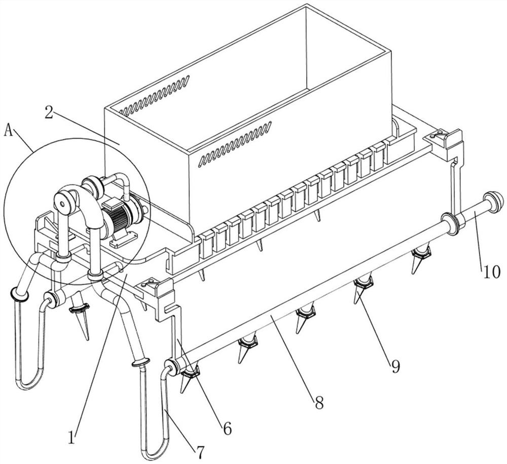
[0037] A kind of self-propelled edible mushroom micro-spray humidifier, such as Figure 1-4 As shown, it includes a bottom plate 1, a water tank 2, a water pump 3, a guide pipe 4, a first fixed column 5, a second fixed column 6, a first flexible pipe 7, a first water delivery pipe 8, a first spray nozzle 9, Rotating rod 10, moving mechanism 11 and steering mechanism 12, bottom plate 1 top is provided with water tank 2, and bottom plate 1 top left side is provided with water pump 3, and water pump 3 right side is connected with water tank 2, and bottom plate 1 top left side is provided with the front and rear symmetrical type. One fixed column 5, the first fixed column 5 is located at the lower side of the water pump 3, a guide tube 4 is connected between the two first fixed columns 5, the upper side of the guide tube 4 communicates with the water pump 3, the front and rear sides of the bottom plate 1 are The left-right symmetrical type is provided with the second fixed post 6,...
Embodiment 2
[0040] On the basis of Example 1, such as Figure 1-2 and Figure 5-7 As shown, the moving mechanism 11 includes a mounting plate 111, a third fixed column 112, a fourth fixed column 113, a first motor 114, a screw 115, a first slider 116, a second slider 117 and a first slider 118 , there is a first slider 116 in the middle of the bottom right side of the bottom plate 1, and a screw rod 115 is rotated on the first slider 116, and a second slider 117 is arranged in the middle of the bottom left side of the bottom plate 1, and the second slider 117 slides The formula is provided with a first slide bar 118, the screw rod 115 and the first slide bar 118 are connected with the third fixed column 112 on the front and rear sides, and the installation plate 111 is connected between the third fixed columns 112 on the front and rear sides. The front side of the inner wall of the mounting plate 111 is provided with a fourth fixed post 113 , and a first motor 114 is provided on the four...
Embodiment 3
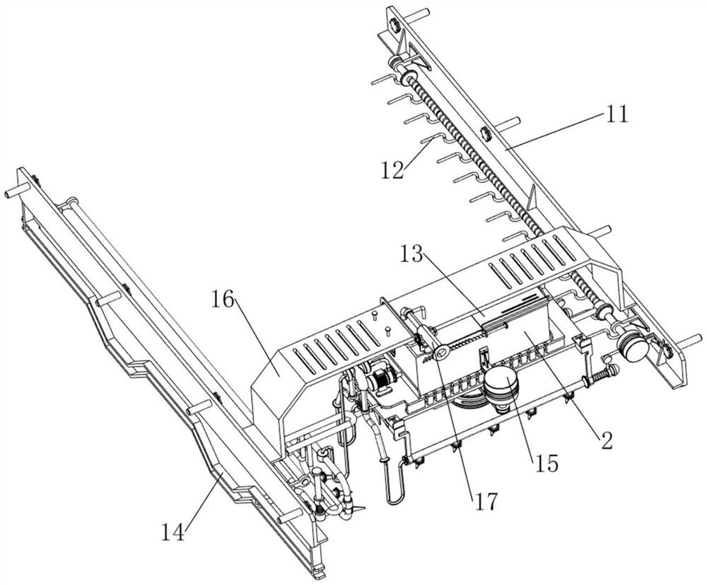
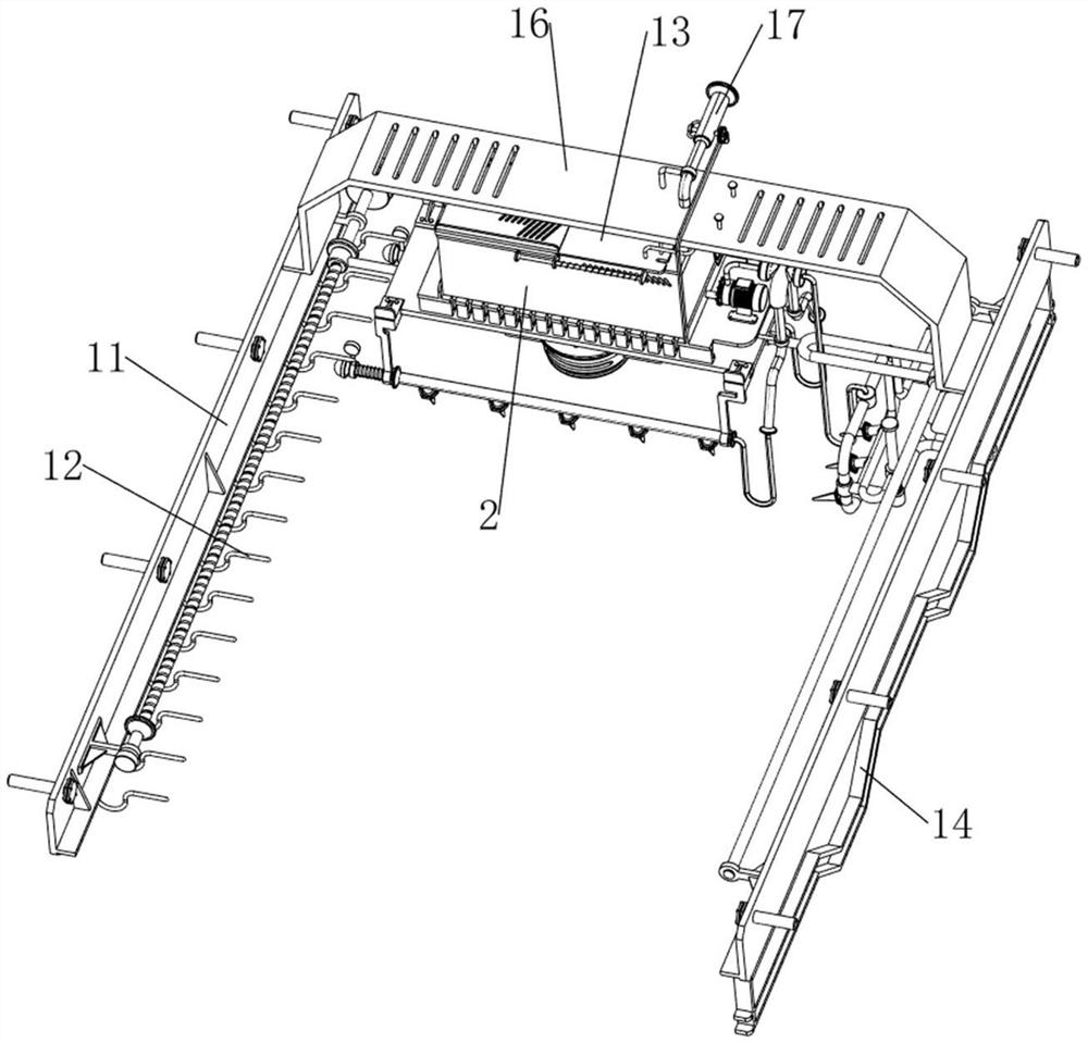
[0045] On the basis of Example 2, such as Figure 1-2 and Figure 8-17 As shown, a cover mechanism 13 is also included. The cover mechanism 13 includes a first cover plate 131, a second cover plate 132 and a pull rod 133. The right side of the top of the water tank 2 is provided with a first cover plate 131, and the first cover plate 131 The upper sliding type is provided with a second cover plate 132 , and the top left side of the second cover plate 132 is provided with a pull rod 133 .
[0046] When the user needs to fill the water tank 2, the second cover 132 can be pulled to the right through the pull rod 133, and then the water tank 2 can be filled with water. After the water filling is completed, the second cover 132 can be reversely moved and closed by the pull rod 133 That is, the floating objects in the air can be prevented from falling in the water tank 2 like this.
[0047] Also includes a side spray mechanism 14, the side spray mechanism 14 includes a limit plate...
PUM
 Abstract
Description
Claims
Application Information
 - Generate Ideas
- Intellectual Property
- Life Sciences
- Materials
- Tech Scout
- Unparalleled Data Quality
- Higher Quality Content
- 60% Fewer Hallucinations
Browse by: Latest US Patents, China's latest patents, Technical Efficacy Thesaurus, Application Domain, Technology Topic, Popular Technical Reports.
© 2025 PatSnap. All rights reserved.Legal|Privacy policy|Modern Slavery Act Transparency Statement|Sitemap|About US| Contact US: help@patsnap.com


