
Alternating current-direct current coupling type common mode inductor for direct current inversion power supply system

A common-mode inductor and power supply system technology, which is applied in the direction of inductors with magnetic cores, transformer/inductor parts, inductors, etc., can solve the problem of damaging system economy and versatility, increasing the volume of DC inverter power supply systems, Unfavorable system practical application and other issues

Active Publication Date: 2021-09-10
XIDIAN UNIV
View PDF13 Cites 0 Cited by
  • Summary
  • Abstract
  • Description
  • Claims
  • Application Information

AI Technical Summary

Problems solved by technology

For example, the application publication number is CN108039815A, and the patent application titled "An Electromagnetic Interference Circuit and Its Operation Method" discloses a circuit for suppressing the common-mode current on both sides of the inverter; the invention is on the DC bus of the inverter A common-mode inductor on the DC side is formed by a magnetic ring, which is used to suppress the common-mode current on the DC side of the inverter; at the same time, a common-mode inductor and a magnetic ring are connected in series on the AC side to suppress the common-mode current on the AC side of the inverter; although the invention can Effectively suppress the common-mode current on both sides of the inverter at the same time, but it only achieves this goal by increasing the number of common-mode inductors, which will greatly increase the volume of the DC inverter power supply system and seriously damage the economy of the system and versatility, which is not conducive to the practical application of the system

Method used


Image

  • Alternating current-direct current coupling type common mode inductor for direct current inversion power supply system
  • Alternating current-direct current coupling type common mode inductor for direct current inversion power supply system

Examples


Embodiment Construction

[0018] The present invention will be further described in detail below in conjunction with the accompanying drawings and specific embodiments.

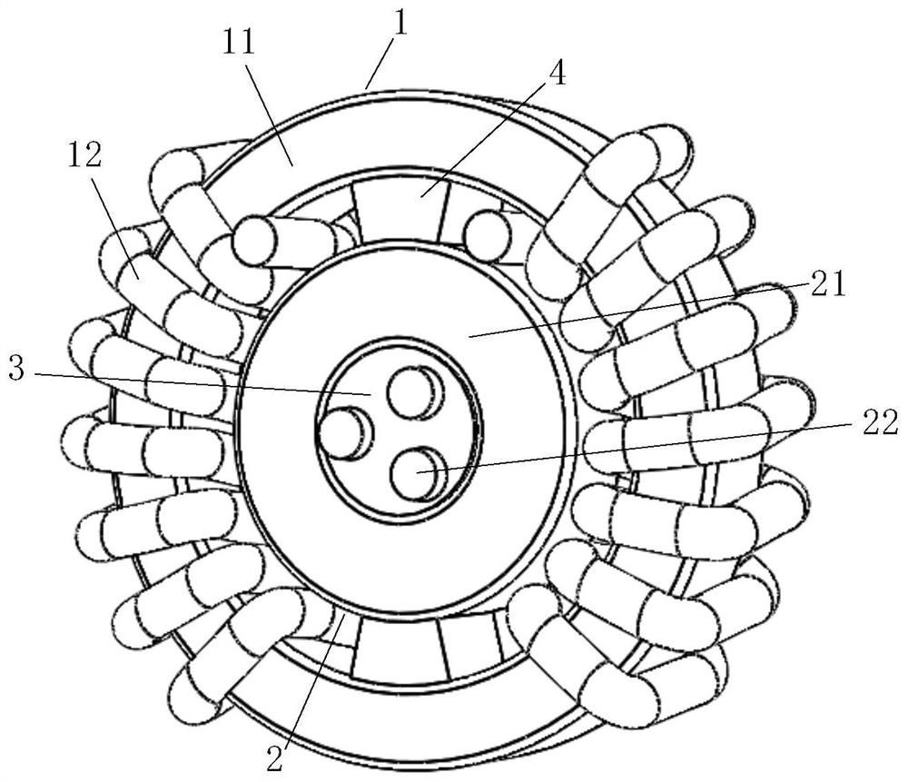
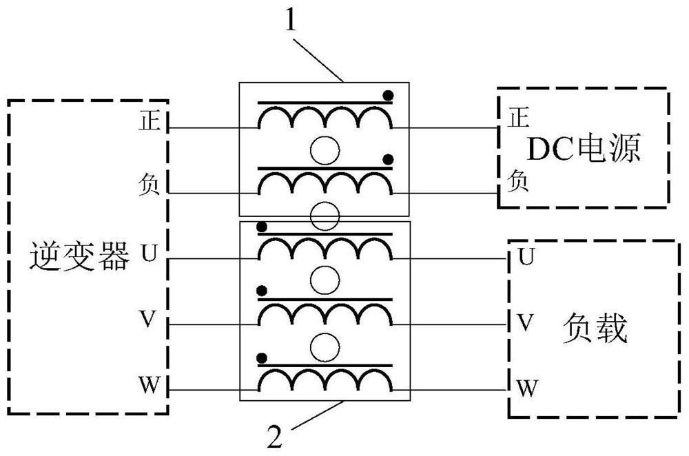
[0019] refer to figure 1 , the present invention includes a DC-side common-mode inductor 1 and an AC-side common-mode inductor 2 .

[0020] The DC-side common mode inductor 1 includes a ring-shaped first magnetic core 11 and two windings 12 wound on the first magnetic core 11; in order to facilitate the combination of two common mode inductors, the first The magnetic core 11 adopts a circular magnetic core with a circular cross section; in order to make the common mode inductor have sufficient anti-saturation capability and filtering capability, the first magnetic core 11 in this embodiment has an initial magnetic permeability of 60,000 and a saturation magnetic induction of The nanocrystalline magnetic core of 1.2T; The two windings 12 wound on the first magnetic core 11, in order to make the common mode inductance can withstand lar...


PUM


Abstract

The invention provides an alternating current-direct current coupling type common mode inductor for a direct current inverter power supply system. The alternating current-direct current coupling type common mode inductor comprises a direct current side common mode inductor (1) and an alternating current side common mode inductor (2); the direct current side common mode inductor (1) comprises an annular first magnetic core (11) and two windings (12) which are wound on the first magnetic core (11) and have the same direction; and the alternating current side common mode inductor (2) comprises an annular second magnetic core (21) and two or three alternating current phase lines (22) penetrating through a window of the second magnetic core (21). According to the alternating current and direct current coupling type common mode inductor for the direct current inversion power supply system of the invention, the second magnetic core (21) is supported and nested in the window of the first magnetic core (11) through an insulating material (4), and coupling of the direct current side common mode inductor (1) and the alternating current side common mode inductor (2)of an inverter is realized, so that the size miniaturization of the alternating current-direct current coupling type common mode inductor is realized on the premise of ensuring effective suppression of common-mode currents at the alternating current side and the direct current side of the direct current inversion power supply system.

Description

technical field [0001] The invention belongs to the technical field of power electronics and relates to an AC-DC coupled common-mode inductor, which is suitable for a DC inverter power supply system. Background technique [0002] A DC inverter power supply system usually consists of a DC power supply, an inverter and a load; when the system is in normal operation, the inverter converts DC power into AC power for the load through PWM pulse width modulation technology; although this modulation technology can be used in many Reduce the loss of the system to a large extent and reduce the demand for heat dissipation of the system, but the disadvantage is that this method will make the switching device in the inverter always work in a high-frequency switching state, and its rapid turn-on and turn-off will A steep pulse with a very high amplitude is formed, resulting in serious electromagnetic interference, which is the main source of interference in the DC inverter power supply sy...

Claims


Application Information

Patent Timeline
IPC IPC(8): H01F17/06H01F27/30H02M1/12H02M1/44
CPCH01F17/062H01F27/306H02M1/12H02M1/44H01F2017/0093
Inventor 郑峰王安宇武志强高天
Owner XIDIAN UNIV
Learn More