
Control method of steam system

A control method and technology of a steam system, which is applied in the field of steam heating and cooking, and can solve problems such as unfavorable steam system energy saving and emission reduction, inability to control steam generator steam, etc.

Active Publication Date: 2021-09-10
珠海歌林能源科技有限公司
View PDF8 Cites 0 Cited by
  • Summary
  • Abstract
  • Description
  • Claims
  • Application Information

AI Technical Summary

Problems solved by technology

[0002]Steam systems generally include steam generators, steam cabinets and other equipment. The steam generator is equipped with a water tank and a combustion heat exchange chamber to heat the water in the water tank to generate steam , the steam is transported to the steam cabinet for heating; the existing steam system generally cannot control the amount of steam generated in the steam generator. The pressure relief valve on the steam cabinet is discharged to avoid accidents. The directly discharged steam will cause energy loss, which is not conducive to the energy saving and emission reduction of the entire steam system

Method used


Image

  • Control method of steam system

Examples


Embodiment 1

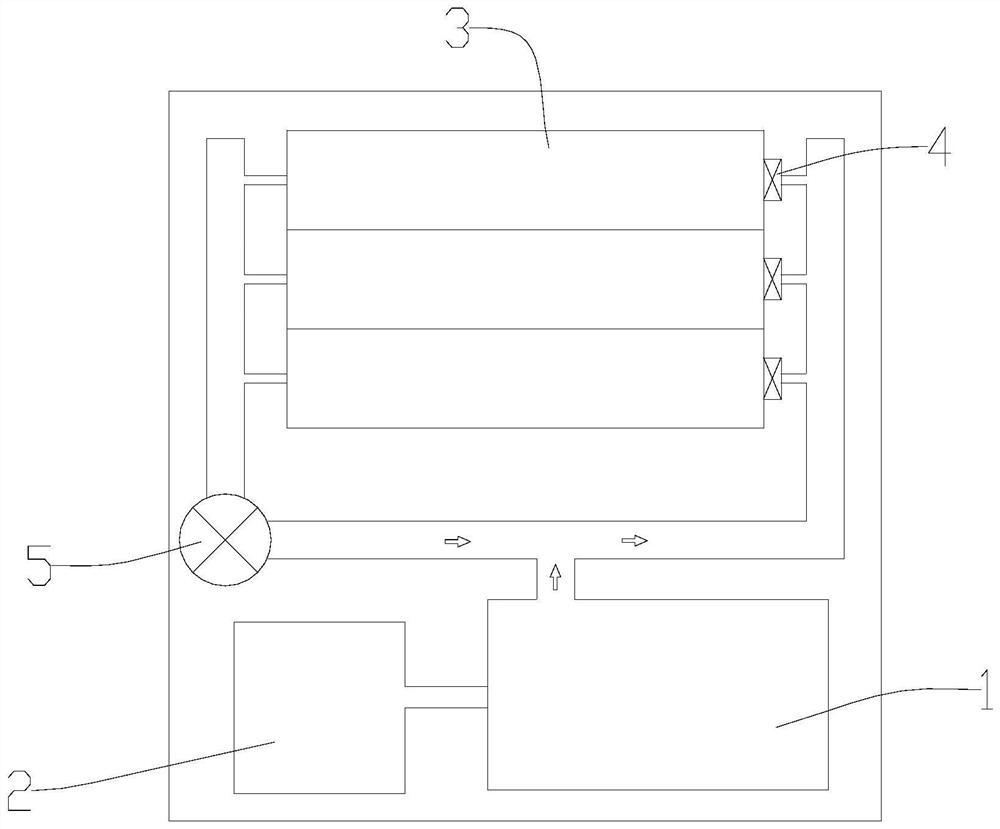
[0026] A method for controlling a steam system, comprising a steam generator 1, a steam cabinet, a fan and a proportional valve; providing premixed gas 2 to the steam generator 1 through the fan and the proportional valve, forming a steam circuit in the steam cabinet, The steam generator 1 generates steam and delivers the steam to the steam circuit. There are a plurality of unit cabinets 3 in the steam cabinet, and each unit cabinet 3 is provided with a temperature sensor. The steam circuit A steam branch is respectively formed to communicate with each unit cabinet 3, and the unit cabinet 3 is provided with a steam valve 4 at the steam inlet connected to the steam branch, and the steam valve 4 is used to open or close the unit cabinet The corresponding steam branch of body 3; Described control method comprises the following steps:

[0027] Controlling the speed change of the fan to form a plurality of wind speed gears, there are high-speed gears and low-speed gears in the gear...

Embodiment 2

[0034] Such as figure 1 As shown, a more preferred implementation is provided on the basis of Example 1. The steam cabinet is provided with three unit cabinets 3, and the temperature sensor and steam valve 4 are arranged in accordance with the number of unit cabinets 3, so Described control method comprises the following steps:

[0035] Controlling the rotation speed of the fan to form at least six wind speed gears, the wind speed of the gears from low to high includes the first low speed gear, the second low speed gear, the third low speed gear, the first high speed gear, and the second high speed gear. gear and the third high-speed gear;

[0036] Detect the state of the steam valve 4 to determine the number of unit cabinets 3 in operation;

[0037]When the number of unit cabinets 3 in operation is 1, match the first low-speed gear and the first high-speed gear; if the measured temperature is less than or equal to the set lower limit temperature, switch the gear of the fan ...

Embodiment 3

[0041] On the basis of Embodiment 1 and Embodiment 2, the energy-saving effect of the steam system is further improved.

[0042] Described steam generator 1 comprises water tank, and described water tank is provided with blowdown valve and water level sensor, and described water level sensor is used for sensing the water level in described water tank, and described control method comprises the following steps:

[0043] Open the sewage valve to discharge sewage. When the water level sensor senses that the water level signal in the water tank is lower than the set low water level signal, and maintains the state of being lower than the set low water level signal for the first set time, it is judged that the sewage is completed. . Sewage with impurities such as solid residues will remain in the water tank of the general steam generator 1. If the sewage is not removed in time, it will greatly affect the heat exchange efficiency and life of the steam generator 1, and the existing st...


PUM


Abstract

The invention relates to a control method of a steam system, which comprises the following steps: controlling rotating speed change of a fan to form a plurality of wind speed gears, wherein the gears comprise a high-speed gear and a low-speed gear, and the valve opening degree of a proportional valve is changed along with the wind speed; detecting the state of a steam valve to determine the number of unit cabinets in work, and enabling the high-speed gear and the low-speed gear to be matched according to the number of the unit cabinets in work; enabling temperature sensors in the unit cabinet bodies in work to sense the temperature in the unit cabinet bodies to obtain the measured temperature, and switching the gear of the fan to the high-speed gear if any obtained measured temperature is smaller than or equal to the set lower limit temperature; and if all the obtained measured temperatures are larger than or equal to the set upper limit temperature, switching the gear of the fan to the low-speed gear. According to the control method of the steam system provided in the invention, the energy consumption of the steam system is reduced through the control mode, and the effects of energy conservation and emission reduction are achieved.

Description

technical field [0001] The invention relates to the field of steam heating cooking, in particular to a method for controlling a steam system. Background technique [0002] The steam system generally includes steam generators, steam cabinets and other equipment. The steam generator is equipped with a water tank and a combustion heat exchange chamber, so that the water in the water tank is heated to generate steam, and the steam is transported to the steam cabinet for heating; the existing steam system generally The amount of steam generated in the steam generator cannot be controlled. When too much steam is generated and transported to the steam cabinet, because the pressure in the steam cabinet is too high, the steam will be discharged through the pressure relief valve on the steam cabinet to avoid accidents and be discharged directly. Steam leads to energy loss, which is not conducive to the energy saving and emission reduction of the entire steam system. Contents of the ...

Claims


Application Information

Patent Timeline
Patent Type & Authority Applications(China)
IPC IPC(8): F22B1/22F22B35/00F22B37/54F23N1/02
CPCF22B1/22F22B35/00F22B37/54F23N1/02
Inventor 邓延鸿
Owner 珠海歌林能源科技有限公司
Learn More