Eureka AIR delivers breakthrough ideas for toughest innovation challenges, trusted by R&D personnel around the world.

Non-return valve assembly and pumping-filling pipeline system

A pipeline system and check valve technology, applied in the direction of filling, sliding valve, valve details, etc., can solve the problems of reducing work efficiency, etc., and achieve the effect of solving the impact of slurry backflow, preventing slurry backflow, and preventing pressure relief

Pending Publication Date: 2018-02-23
FENY
View PDF0 Cites 2 Cited by
  • Summary
  • Abstract
  • Description
  • Claims
  • Application Information

AI Technical Summary

Problems solved by technology

Therefore, this determines that the filling slurry at a high position will have a certain impact on the S-valve piston filling industrial pump when filling the slurry upward, reducing the working efficiency.

Method used


Image

  • Non-return valve assembly and pumping-filling pipeline system
  • Non-return valve assembly and pumping-filling pipeline system
  • Non-return valve assembly and pumping-filling pipeline system

Examples


Embodiment Construction

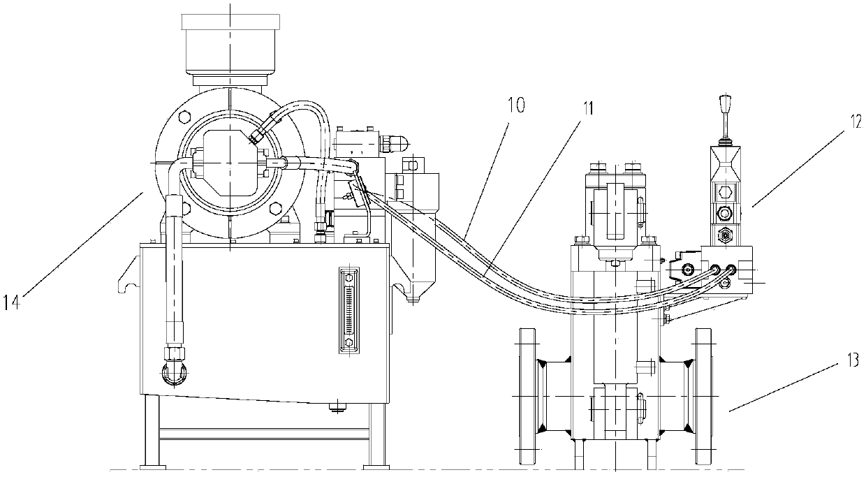
[0050]Aiming at the characteristics of the filling slurry in the pumping filling pipeline system and the pressure in the filling pipeline, as well as the structural principle of the S-valve piston filling industrial pump, the present invention provides a new type of check valve suitable for the above working conditions The assembly, and a pumping and filling pipeline system provided with the check valve assembly can prevent the impact of the filling slurry on the S-valve type piston filling industrial pump.

[0051] The following will clearly and completely describe the technical solutions in the embodiments of the present invention with reference to the accompanying drawings in the embodiments of the present invention. Obviously, the described embodiments are only some, not all, embodiments of the present invention. Based on the embodiments of the present invention, all other embodiments obtained by persons of ordinary skill in the art without making creative efforts belong to...


PUM


Abstract

The invention discloses a non-return valve assembly and a pumping-filling pipeline system provided with the non-return valve assembly. According to the non-return valve assembly and the pumping-filling pipeline system, impact of filling slurry on an S-valve-type piston-type filling industrial pump can be avoided. The non-return valve assembly comprises a valve body and a first electromagnetic reversing valve set. The valve body comprises a shell, a valve element and valve body oil cylinders. A feeding inlet in the shell is matched with an outlet of the S-valve-type piston-type filling industrial pump in the pumping-filling pipeline system. When the valve body oil cylinders drive the valve element to move to the limiting position in the shell, the shell is closed, and when the valve body oil cylinders drive the valve element to leave the limiting position, the shell communicates; the first electromagnetic reversing valve set is used for controlling the valve body oil cylinders; and an Spipe in the S-valve-type piston-type filling industrial pump is driven by a swinging oil cylinder to swing, the swinging oil cylinder is controlled by a second electromagnetic reversing valve set, and the first electromagnetic reversing valve set and the second electromagnetic reversing valve set are connected in parallel and makes action synchronously.

Description

technical field [0001] The invention relates to the technical field of mine paste filling, in particular to a check valve assembly and a pumping filling pipeline system provided with the check valve assembly. Background technique [0002] Paste filling is to make mine tailings, gravel, fly ash, industrial slag and other solid waste into a paste-like slurry that does not need to be dehydrated, and transport it to the underground filling area through pipelines through pump pressure or gravity. In the paste filling system, according to the filling process, it can generally be divided into 5 subsystems, namely tailings slurry thickening system, aggregate crushing and screening system, filling slurry mixing preparation system, pumping filling pipeline system, electrical control system etc. [0003] In the paste filling system, some filling stations are built below the filling roadway, and the filling pipeline must be arranged upward along the slope. In this way, the filling slu...

Claims


Application Information

Patent Timeline
Patent Type & Authority Applications(China)
IPC IPC(8): F16K3/00F16K31/12F15B1/02F15B11/16F15B13/06E21F15/10
CPCE21F15/10F15B1/02F15B11/16F15B13/06F16K3/00F16K31/12F15B2211/212F15B2211/20538
Inventor 姜寄杨良庚肖崇春陶平张志伟
Owner FENY
Why Eureka
Eureka Blog
Learn More