Supporting device capable of adjusting elevation of bent cap end chamfering formwork and construction technology

A supporting device and adjustable technology, which is applied in the direction of bridges, bridge construction, erection/assembly of bridges, etc., can solve the problems of limited use scenarios and inability to adjust the elevation of the vertical formwork

Active Publication Date: 2021-09-10
CHINA CONSTR FIRST BUILDING GRP CORP LTD +1
View PDF11 Cites 2 Cited by
  • Summary
  • Abstract
  • Description
  • Claims
  • Application Information

AI Technical Summary

Problems solved by technology

The support device of the adjustable cover beam end chamfering formwork in the above-mentioned patent has the following disadvantages: the fixed support device can adjust the inclination angle, but the elevation of the vertical formwork cannot be adjusted according to the actual application situation on site, so the use scene is limited

Method used


Image

  • Supporting device capable of adjusting elevation of bent cap end chamfering formwork and construction technology
  • Supporting device capable of adjusting elevation of bent cap end chamfering formwork and construction technology
  • Supporting device capable of adjusting elevation of bent cap end chamfering formwork and construction technology

Examples


Embodiment 1

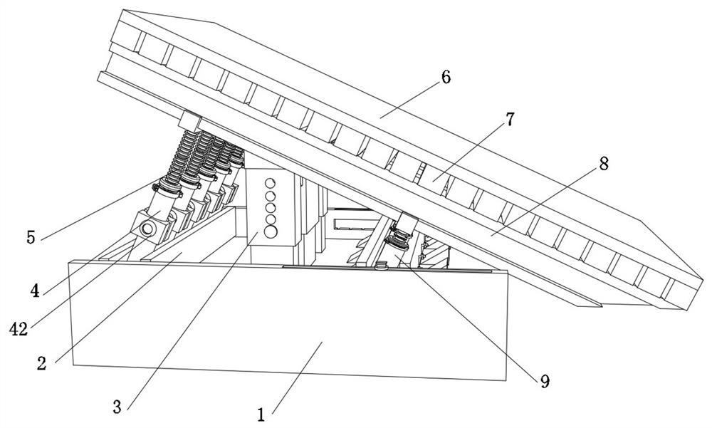
[0047] A support device that can adjust the height of the chamfering formwork at the end of the cover beam, such as figure 1 , figure 2 , Figure 4 and Figure 7 As shown, it includes two first I-beams 2, the top outer walls of the two first I-beams 2 are provided with a plurality of circular grooves, and the circumferential inner walls of the multiple circular grooves are all fixed with elastic shrink covers 23 by bolts. The inner wall of the elastic shrink cover 23 is welded with a rubber block 22, and the outer wall of the elastic shrink cover 23 is fixed with two elastic connectors 30 by bolts. One end of the two elastic connectors 30 is respectively fixed to the same first I-beam 2 by bolts the inner wall on the opposite side. Two sets of inclined holes 13 are provided on one side of the first I-beam 2, and the number of each set of inclined holes 13 is not less than two. Preferably, in this embodiment, the number of inclined holes 13 in each set is The number is thr...

Embodiment 2

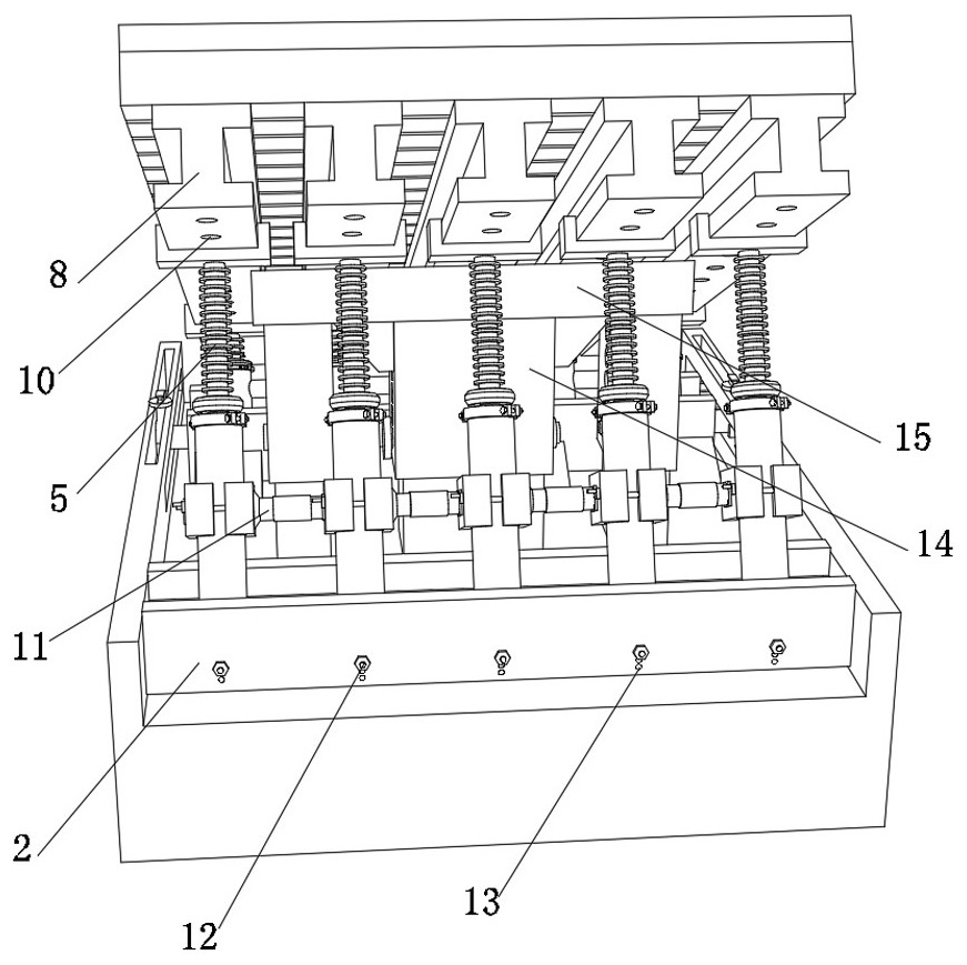
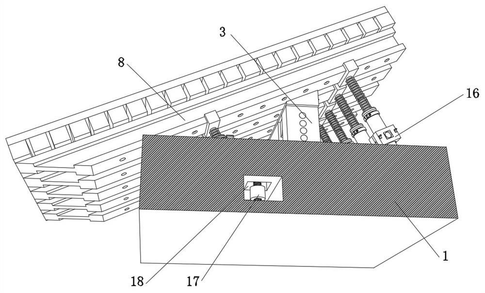
[0052] A support device that can adjust the height of the chamfered formwork at the end of the cover beam. In order to effectively avoid the deformation of the load-bearing structure during use, such as Figure 1-6 As shown, the bottom outer wall of one of the first I-beams 2 is fixed with a base 1 by bolts, and the bottom outer walls of a plurality of second I-beams 8 are fixed with the same backing plate 15 by bolts, and the backing plate 15 The outer wall of the bottom is fixed with at least two adjustment columns 3 by bolts, and the outer wall of the backing plate 15 close to the bottom of the two adjustment columns 3 is fixed with a second adjustment column 14 by bolts, and the outer walls on both sides of the second adjustment column 14 are fixed with reinforcement by bolts. The corner plate, the extension ends of the two adjustment columns 3 and the extension end of the second adjustment column 14 are all plugged into the top outer wall of the base 1; the bottom inner wa...

Embodiment 3

[0056] A construction technique for the support device of the adjustable cover beam end chamfering formwork elevation described in Embodiment 1 and Embodiment 2, such as Figure 1-11 shown, including the following steps:

[0057] S1: install the first steel pipe 4 and the second steel pipe 9 with the two first I-beams 2 respectively, and adjust the inclination angle through the positioning pin 12 and the shackle 31;

[0058] S2: install the threaded column 5 in the first steel pipe 4 and the second steel pipe 9, and install connecting structures and connecting columns between the plurality of first steel pipes 4 and the plurality of second steel pipes 9;

[0059] S3: Adjust the position of one of the first I-beams 2 in the two long grooves 19, and use the limit plate 20 to limit the position;

[0060] S4: Fix the load-bearing structure on the threaded column 5, and rotate the threaded column 5 to operate and adjust the height of the chamfering formwork;

[0061] S5: adjust t...


PUM


Abstract

The invention discloses a supporting device capable of adjusting the elevation of a bent cap end chamfering formwork and a construction technology, and relates to the technical field of highway and municipal bridge construction tools. In order to solve the problem that the elevation of a standing mold cannot be adjusted, the supporting device comprises two first I-shaped steel, a plurality of circular grooves are formed in the outer walls of the tops of the two first I-shaped steel, and elastic contraction covers are arranged on the circumferential inner walls of the circular grooves. The construction technology of the supporting device comprises the following steps that first steel pipes and second steel pipes are installed with the two pieces of first I-shaped steel correspondingly, and the use dip angle is adjusted through positioning pin columns and hook rings; and threaded columns are installed in the first steel pipes and the second steel pipes, and connecting structures and connecting columns are installed between the multiple first steel pipes and between the multiple second steel pipes correspondingly. The overall elevation or one-end elevation or inclination angle of the bearing structure can be conveniently adjusted according to actual requirements, the application range is expanded, the operation is flexible, and the construction period can be effectively shortened when the device is applied to the site.

Description

technical field [0001] The invention relates to the technical field of construction tools for highways and municipal bridges, in particular to a support device and a construction process capable of adjusting the elevation of a chamfering formwork at the end of a cover beam. Background technique [0002] In highway and municipal bridge projects, especially simply supported bridges, the cover beam is an important component connecting the upper and lower structures. The load of the upper structure is transmitted to the lower structure and foundation through the cover beam. The cover beam is the main force-bearing structure, while the conventional cover beam The end formwork of the cover beam is usually a fixed steel frame. The existing cap beam end chamfering device is welded by I-beam or steel bar. It is a fixed cap beam end chamfering device, but in actual use , the fixed formwork support at the end of the cover beam welded by I-beam or steel bars has a single adaptability. W...

Claims


Application Information

Patent Timeline
Patent Type & Authority Applications(China)
IPC IPC(8): E01D21/00
CPCE01D21/00
Inventor 戚培海张勇刚匡丕榜李玲珑廖良雄刘玥岩王鹏乔建徽李明斌亚非徐铮张海山彭霖
Owner CHINA CONSTR FIRST BUILDING GRP CORP LTD
Why Eureka
Try Eureka