
Automatic plate cutting, bending and welding equipment

A technology of automatic cutting and welding equipment, applied in other manufacturing equipment/tools, metal processing, manipulators, etc., can solve problems such as low grasping efficiency and lack of automated processes

Pending Publication Date: 2021-09-10
马鞍山市安工大智能装备技术研究院有限公司
View PDF0 Cites 2 Cited by
  • Summary
  • Abstract
  • Description
  • Claims
  • Application Information

AI Technical Summary

Problems solved by technology

The existing technology also discloses a method of placing various grippers for grabbing the plate to be cut, the finished plate after cutting, and the remaining material of the plate in the gripper spare parts warehouse by means of quick change, and the end of the robot body is transported. The flange and the above-mentioned grippers are connected sequentially by quick change. This method can reduce the number of handling robots, but the gripping efficiency is low
[0003] After the existing plate is automatically cut, there is a lack of continuous automation process, and it is necessary to manually participate in the turnover of materials, and then enter the subsequent bending process. After bending, the turnover of materials is manually performed, placed on the welding positioning tool, and the welding robot performs welding

Method used


Image

  • Automatic plate cutting, bending and welding equipment
  • Automatic plate cutting, bending and welding equipment
  • Automatic plate cutting, bending and welding equipment

Examples


Embodiment Construction

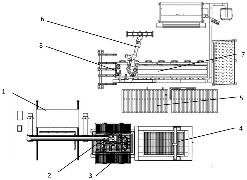
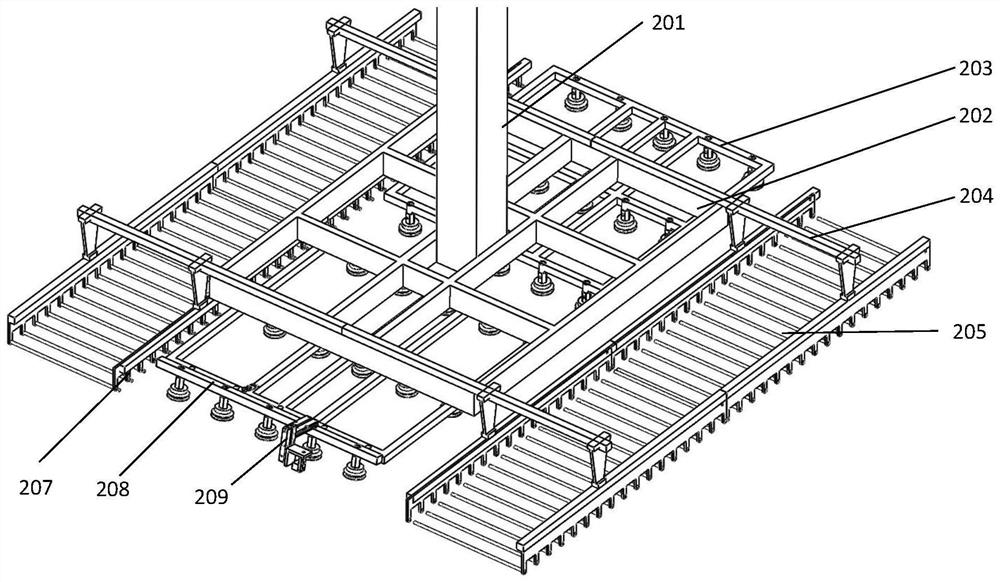
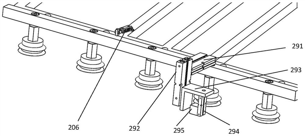
[0023] Such as Figure 1-Figure 6 As shown, a plate automatic cutting, bending and welding equipment includes a plate incoming warehouse 1, a first handling manipulator 2, a laser cutting robot 4, a second handling manipulator and a bending robot 6, and two transplanting workbenches 3 are respectively set Below and on one side of the laser cutting robot 4, the first transport manipulator 2 includes a first transport manipulator body and a first transport gripper, the first transport gripper includes a gripper installation base frame 202, a suction mechanism and a gripping mechanism, The upper part of the gripper installation base frame 202 is fixedly connected with the lower part of the gripper connecting rod 201, and the upper part of the gripper connecting rod 201 is fixed on the end flange of the first handling manipulator body, and the suction mechanism is installed on the lower part of the gripper installation base frame 202, and the gripper The picking mechanism is arran...


PUM


Abstract

The invention discloses automatic plate cutting, bending and welding equipment, and belongs to the technical field of automatic machining equipment. The automatic plate cutting, bending and welding equipment comprises a first carrying robot body and a first carrying gripper, the upper portion of a gripper mounting base frame is connected with a tail end flange of the first carrying robot body, and a suction mechanism is mounted on the lower portion of the gripper mounting base frame. Grabbing mechanisms are located on the two sides of the suction mechanism correspondingly, the suction mechanism sucks plates from a plate feeding warehouse and places the plates on a transplanting workbench, the transplanting workbench conveys the plates into a laser cutting robot for machining, and the grabbing mechanisms on the two sides get close to each other to grab the cut plates and place the cut plates on a transfer platform. A bending robot is used for conveying cut finished products from the transfer platform to a bending machine to be bent, then the bent finished products are placed in a welding transfer frame, and a welding robot is used for welding the bent finished products positioned on welding tool tables. The equipment can realize automatic cutting, bending and welding of the plates, and is high in production continuity.

Description

technical field [0001] The invention belongs to the technical field of automatic processing equipment, and in particular relates to equipment for automatic cutting, bending, welding and continuous production of plates. Background technique [0002] In the existing sheet metal laser cutting process, two transplanting worktables are respectively set under the laser cutting robot and on the side close to the sheet material handling robot. On the planting workbench, the two transplanting workbenches move relative to each other to exchange positions. The transplanting workbench drives the plate to move directly under the laser cutting robot, and the laser cutting robot processes and cuts the plate below it according to the preset trajectory. The cut plate (including the finished product and the remaining plate material) is placed on the transplanting table outside the cutting robot. In the existing automatic laser cutting of the plate, two plate handling manipulators are usually ...

Claims


Application Information

Patent Timeline
IPC IPC(8): B23P23/00B23Q7/00B23Q7/04B25J15/00B25J15/06
CPCB23P23/00B23Q7/00B23Q7/04B25J15/00B25J15/0616
Inventor 王璐盛乾超孟瑞汪超谢能刚
Owner 马鞍山市安工大智能装备技术研究院有限公司
Learn More