Axial driving mechanism, automatic injection device and use method of automatic injection device

An axial drive, sliding groove technology, applied in the direction of automatic injectors, syringes, hypodermic instruments, etc., can solve problems such as violation of ergonomics, the product cannot be guaranteed to self-lock after the product, and the patient forgets to operate.

Active Publication Date: 2021-09-10
NINGBO COMFORT-INFUSTION MEDTECH CO LTD
View PDF8 Cites 5 Cited by
  • Summary
  • Abstract
  • Description
  • Claims
  • Application Information

AI Technical Summary

Problems solved by technology

However, in some specific cases, there will be phenomena such as loss of limiting parts and patients forgetting to operate, so that the product cannot ensure that it is self-locking after use.
And this design is contrary to human factors engineering and does not conform to the design characteristics of this type of product
[0007] 5. Existing products often can only judge whether the liquid medicine has been injected by viewing the position of the piston or push rod in the prefilled syringe through the observation window. However, due to various restrictions, it is impossible to accurately judge whether the liquid medicine has been completely injected like traditional manual injection. complete
However, in this invention, the stopping elements used for vocal feedback are continuously distributed, and they are always vocal from the beginning of the injection to the end of the injection, and there is no obvious distinction, which is likely to cause confusion for the patient and cannot accurately identify the injection state

Method used


Image

  • Axial driving mechanism, automatic injection device and use method of automatic injection device
  • Axial driving mechanism, automatic injection device and use method of automatic injection device
  • Axial driving mechanism, automatic injection device and use method of automatic injection device

Examples


Embodiment 1

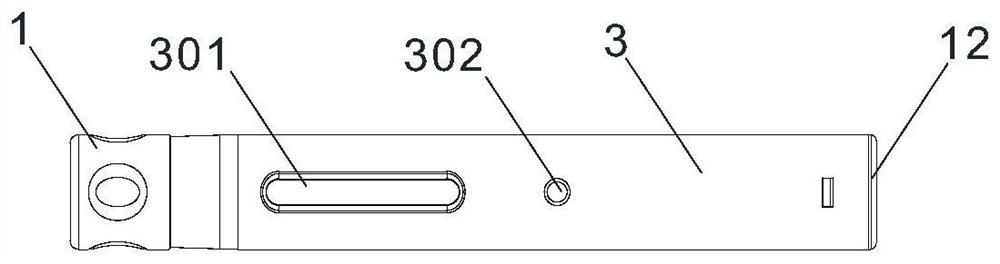
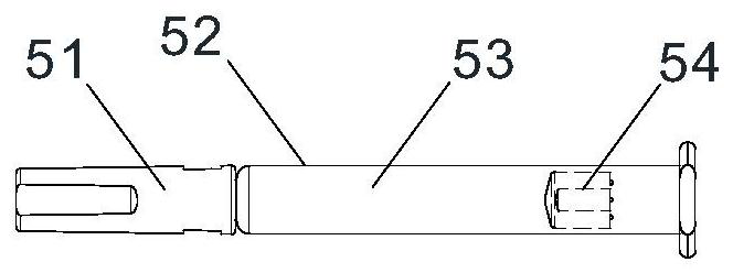
[0086] Such as Figure 1 to Figure 6b , Figure 7a to Figure 17 As shown, an automatic injection device with double visual feedback, including a head-end protective cap 1, a safety sleeve 2, a housing 3, a protective case 4, a prefilled syringe 5, a return spring 6, a release sleeve 7, a limit position Sounding ring 8, guide sleeve 9, push rod 10, injection spring 11 and bottom cover 12, injection spring 11 is provided between push rod 10 and bottom cover 12, head end protective cap 1, safety sleeve 2, shell 3 and protection The shell 4 constitutes the shell assembly, the return spring 6, the release sleeve 7, the limit sounding ring 8, the guide sleeve 9, the push rod 10 and the bottom cover 12 constitute an axial drive mechanism with visual feedback. The front end of the push rod 10, That is, the end facing the prefilled syringe 5 is the output end of the axial drive mechanism, and the prefilled syringe 5 and the axial drive mechanism are arranged in the cavity of the housi...

Embodiment 2

[0097] Such as Figure 6c As shown, the front end of the push rod 10 is equipped with a gasket 1004 that can rotate around the axis of the push rod 10. The gasket 1004 plays the role of a plane bearing. When the push rod 10 is pushed forward, the gasket 1004 contacts the piston 54, and the two maintain Relatively stationary, the push rod 10 and the piston 54 rotate relative to each other, which can reduce the resistance encountered during the rotation of the push rod. All the other are with embodiment 1.

Embodiment 3

[0099] Such as Figures 18 to 20d As shown, the tile-shaped long cantilever is provided with a hollow area, the hollow area is provided with a safety sleeve self-locking cantilever 203, and the safety sleeve self-locking cantilever 203 is provided with a self-locking bump 204, and the self-locking structure is set On the housing assembly, the self-locking structure includes a safety sleeve self-locking cantilever 203 provided on the safety sleeve 2 and a lock block 304 provided on the inner wall of the housing 3, and the lock block 304 protrudes radially on the inner wall of the housing 3 , the lock block 304 is V-shaped as a whole, and the lock block 304 is provided with a starting side wall 3041 and a reset side wall 3042 intersecting at the rear end of the lock block 304, and the starting side wall 3041 and the reset side wall 3042 intersect to form a rear sharp point 3045 of the lock block, The front end of the locking block 304 is provided with a V-shaped groove 3043 . T...


PUM


Abstract

The invention discloses a visual-feedback axial driving mechanism. the visual-feedback axial driving mechanism comprises a reset spring, a release sleeve, a push rod and a bottom cover, wherein the reset spring sleeves the release sleeve, and an injection spring is arranged between the push rod and the bottom cover. The axial driving mechanism further comprises a limiting sound production ring and a guide sleeve, wherein the release sleeve, the guide sleeve and the push rod are coaxially nested in a sliding mode, the limiting sound production ring is rotationally connected to the end of the guide sleeve in a sleeving mode and is pushed to rotate by the push rod, the guide sleeve and the push rod can act to generate starting prompt sound in a pushing process of the push rod, the limiting sound production ring and the guide sleeve can act to generate stopping prompt sound, and the limiting sound production ring displays indication marks separately during the starting and stopping of pushing of the push rod. The invention further discloses an automatic injection device with double visual feedback employing the axial driving mechanism and a working method of the automatic injection device with the double visual feedback.

Description

technical field [0001] The present invention relates to a novel drug delivery device for self-management of diseases by patients and its working method, more specifically, it relates to an axial drive mechanism with visual feedback and an automatic injection device using the axial drive mechanism with visual feedback device and its working method. Background technique [0002] With the explosive growth of population, the siphon effect of cities, and the increasing shortage of medical resources, the management of chronic diseases will occupy a large amount of medical resources, resulting in huge economic costs. Society has put forward higher requirements for injection devices used by patients themselves. People hope that the operation of injection devices is as simple as possible and does not require special training. Traditional injection devices usually require proficiency in the angle and depth of needle insertion, and manual injection, resulting in a certain difference i...

Claims


Application Information

Patent Timeline
Patent Type & Authority Applications(China)
IPC IPC(8): A61M5/20A61M5/31A61M5/315A61M5/32
CPCA61M5/2033A61M5/31A61M5/3158A61M5/3202A61M5/3257A61M2205/583A61M2005/31588
Inventor 王佩儿
Owner NINGBO COMFORT-INFUSTION MEDTECH CO LTD
Why Eureka
Try Eureka