
Centrifugal compressor rotor capable of hydraulically assembling and disassembling impeller and impeller assembling and disassembling method

A technology for centrifugal compressors and impellers, applied in liquid fuel engines, parts of pumping devices for elastic fluids, mechanical equipment, etc., can solve problems such as poor repeat assembly accuracy, safety risks, and rotor appearance deterioration. Achieve the effect of avoiding impeller deformation, avoiding damage and precise positioning

Pending Publication Date: 2021-09-07
XIAN SHAANGU POWER
View PDF0 Cites 2 Cited by
  • Summary
  • Abstract
  • Description
  • Claims
  • Application Information

AI Technical Summary

Problems solved by technology

[0004] In view of the deficiencies in the above-mentioned prior art, the object of the present invention is to provide a centrifugal compressor rotor that can hydraulically assemble and disassemble the impeller, so as to solve the problems of difficult assembly and disassembly of the existing centrifugal compressor rotor impeller, easy deformation, and poor repeat assembly accuracy. , the appearance of the rotor deteriorates due to heating, and there are safety risks in the disassembly process, etc.

Method used


Image

  • Centrifugal compressor rotor capable of hydraulically assembling and disassembling impeller and impeller assembling and disassembling method
  • Centrifugal compressor rotor capable of hydraulically assembling and disassembling impeller and impeller assembling and disassembling method
  • Centrifugal compressor rotor capable of hydraulically assembling and disassembling impeller and impeller assembling and disassembling method

Examples


Embodiment Construction

[0031] The invention is applicable to rotors with single-stage, two-stage back-to-back, two-stage parallel arrangement and other structures.

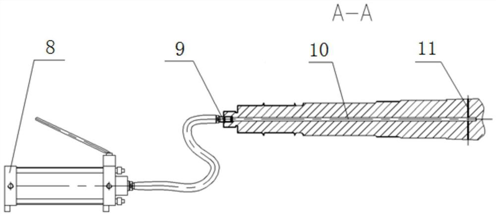
[0032] Such as Figure 1-Figure 3 As shown, the centrifugal compressor rotor of the present invention, which can hydraulically assemble and disassemble the impeller, includes a main shaft 1 , a balance disc 2 , an impeller 3 , a shaft sleeve 4 and a lock nut 5 . Among them, the balance plate 2, the impeller 3, the shaft sleeve 4 and the lock nut 5 are installed on the main shaft 1 in sequence, and the lock nut 5 is connected with the main shaft 1 through threads; the inner hole of the impeller 3 is a conical surface, and the impeller 3 is set on the main shaft , the cone surface of the inner hole of the impeller 3 and the cone surface of the outer wall of the main shaft 1 are interference fit, and the degree of interference is checked and determined according to the rotating speed and the structure of the impeller; the matching cone sur...


PUM


Abstract

The invention discloses a centrifugal compressor rotor capable of hydraulically assembling and disassembling an impeller and an impeller assembling and disassembling method. The centrifugal compressor rotor comprises a main shaft, a balance disc, the impeller, a shaft sleeve and a locking nut, the balance disc, the impeller, the shaft sleeve and the locking nut are sequentially installed on the main shaft, and the locking nut is in threaded connection with the main shaft; the impeller is sleeved on the main shaft; and an annular oil passing groove is arranged on a matched conical surface of the main shaft, an axial oil injection hole is arranged at the axis of the main shaft, one end of the axial oil injection hole is located in a shaft head of the main shaft, and the other end of the axial oil injection hole is communicated with the annular oil passing groove through a radial oil inlet hole. The impeller does not need to be heated by flames in the impeller assembling and disassembling process, operation is simple and safe, and meanwhile, the impeller is prevented from deforming and bluing due to heating in the hot charging process; the impeller is axially positioned and locked through the locking nut, the shaft sleeve and a shaft shoulder structure on the main shaft, so that the axial movement of the impeller in the rotation of the rotor is avoided; and accurate positioning of impeller installation is achieved through a hydraulic tool, damage to the matching face of the impeller and the main shaft caused by disassembly and assembly is avoided, and repeated disassembly and assembly can be achieved.

Description

technical field [0001] The invention belongs to the technical field of centrifugal compressors, and in particular relates to a rotor of a centrifugal compressor which can hydraulically assemble and disassemble an impeller and a method for installing and disassembling the impeller. Background technique [0002] Centrifugal compressors are the core equipment in many key devices in petrochemical, coal chemical, natural gas transmission, metallurgy, fertilizer, pharmaceutical and many other industrial fields, and their operating conditions directly affect the production efficiency of the entire process device. Therefore, the centrifugal compressor must not only meet the requirements of efficient operation, safety and stability for a long period, but also have the characteristics of convenient maintenance and low maintenance cost. [0003] Centrifugal compressor rotor is the main rotating working part of single-shaft centrifugal compressor, which includes main shaft, impeller and...

Claims


Application Information

Patent Timeline
Patent Type & Authority Applications(China)
IPC IPC(8): F04D17/10F04D29/28F04D29/62F04D29/063F04D29/053
CPCF04D17/10F04D29/284F04D29/624F04D29/063F04D29/053
Inventor 汤本凯蔺满相陈余平姚艳朱安安段纪成祁周会王煜马铁锋庞晓斌徐海霞崔佳杰李宇
Owner XIAN SHAANGU POWER
Learn More