
Rod pit tamping device for electric power engineering construction

A technology of electric power engineering and compaction device, which is applied in basic structure engineering, construction, excavation, etc., can solve the problems of time-consuming and laborious, complicated manual compaction process, and no compaction structure on the inner wall of the pole pit.

Active Publication Date: 2021-09-07
QUZHOU UNIV
View PDF6 Cites 1 Cited by
  • Summary
  • Abstract
  • Description
  • Claims
  • Application Information

AI Technical Summary

Problems solved by technology

[0003] In the current electric power engineering construction, two methods of manual compaction and mechanical compaction are usually used for the compaction of pole pits. The manual compaction process is complicated and time-consuming. Although the compaction machine is very efficient when used in flat areas, the traditional compaction machine It is highly targeted and is only suitable for tamping the bottom of the pole pit through the lifting and lowering of the weight after the excavation of the pole pit. There is no tamping structure for the inner wall of the pole pit; at the same time, the existing tamping machinery lacks a The tamping device for the pole pit after the utility poles in the pole pit are buried

Method used


Image

  • Rod pit tamping device for electric power engineering construction
  • Rod pit tamping device for electric power engineering construction
  • Rod pit tamping device for electric power engineering construction

Examples


Embodiment Construction

[0036] The following will clearly and completely describe the technical solutions in the embodiments of the present invention with reference to the accompanying drawings in the embodiments of the present invention. Obviously, the described embodiments are only some, not all, embodiments of the present invention. Based on the embodiments of the present invention, all other embodiments obtained by persons of ordinary skill in the art without creative efforts fall within the protection scope of the present invention.

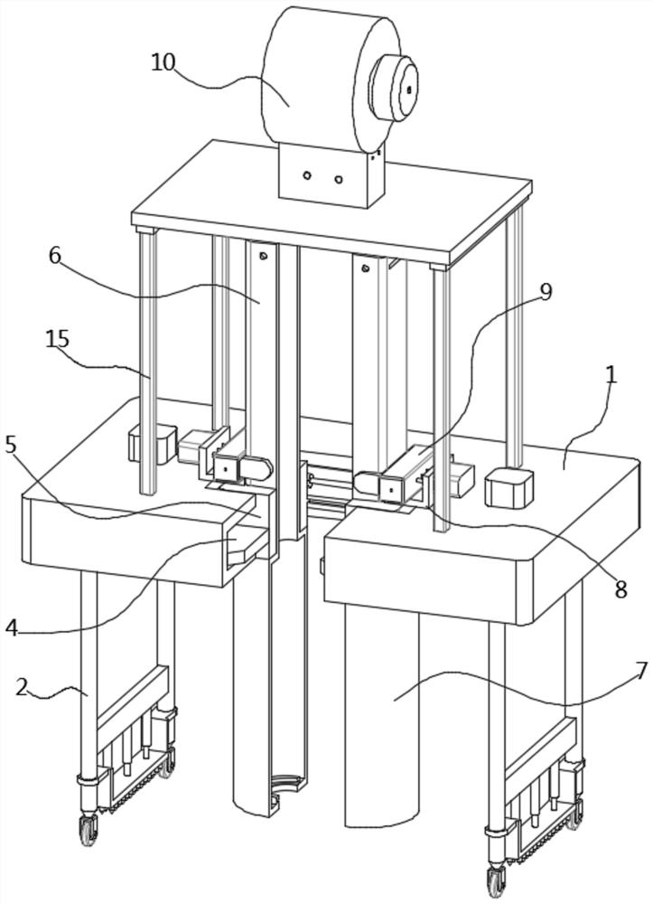
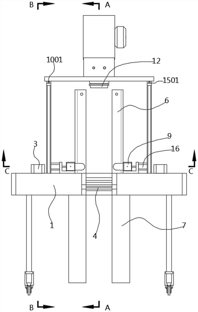
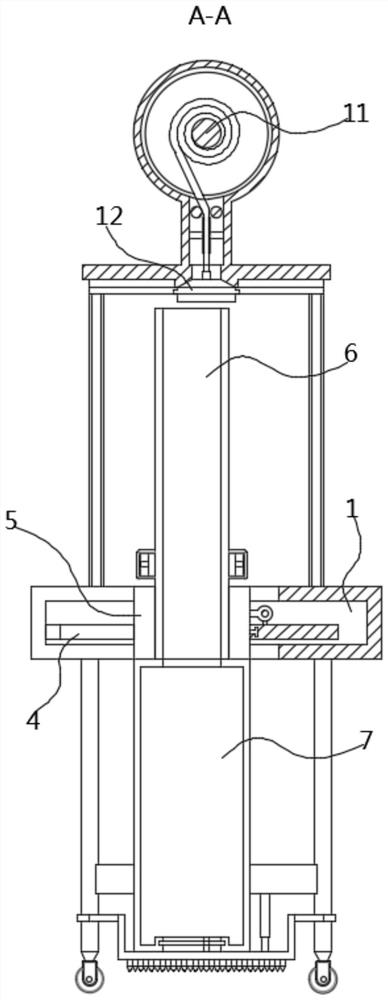
[0037] see Figure 1-12As shown, the present invention is a pole hole tamping device for electric power engineering construction, comprising a frame body 1, both sides of the lower surface of the frame body 1 are fixed with a sliding frame 2, and the bottom of the movable sliding frame 2 is fixedly connected with a row of telescopic rods 201. The nail plate 202, the two ends of the nail plate 202 are respectively sleeved on both sides of the bottom end of the slidi...


PUM


Abstract

The invention discloses a rod pit tamping device for electric power engineering construction, and relates to the technical field of electric power construction. The rod pit tamping device comprises a frame body, sliding frames are fixed to the two sides of the lower surface of the frame body, and nail plates are arranged at the bottoms of the sliding frames; a driving frame is rotationally arranged at the bottom in the frame body; two oppositely-arranged limiting frames are arranged in the driving frame in a sliding fit mode, and a clamping grooves are formed in the limiting frames in a sliding mode; fan-shaped tamping grooves are fixed to the bottom ends of the clamping grooves, and a limiting clamping mechanism clamped to the ends of the clamping grooves is installed at the top end of the limiting frame; the top of the frame is in sliding fit with a winding box, a reel is rotationally arranged on the top in the winding box, a traction rope is wound around the reel, and the bottom end of the traction rope extends out of the winding box and is fixedly provided with a chuck clamped and matched with the fan-shaped tamping grooves. According to the rod pit tamping device, the clamping grooves and the fan-shaped tamping grooves are driven by the driving frame to vibrate circumferentially in a rod pit, the inner wall of the rod pit is tamped, the fan-shaped tamping groove is driven by the chuck to vertically ascend and descend, and the inner bottom is tamped; after a telegraph rod is buried, the rod pit can be tamped through the two fan-shaped tamping grooves.

Description

technical field [0001] The invention belongs to the technical field of electric power construction, and in particular relates to a pole hole tamping device for electric power engineering construction. Background technique [0002] Electric power engineering refers to engineering related to the production, transmission, and distribution of electric energy. In a broad sense, it also includes engineering that uses electricity as power and energy in various fields. The transmission and distribution of electric energy is mainly realized through high and low voltage AC power networks. As the development direction of power transmission engineering technology, the focus is on the study of UHV AC and DC transmission technologies to form a larger power network; at the same time, it is also necessary to study the technical issues of superconductor power transmission. As a form of energy, electric energy has many advantages such as easy conversion, convenient transportation, easy contr...

Claims


Application Information

Patent Timeline
IPC IPC(8): E02D3/046E02D17/08
CPCE02D3/046E02D17/08Y02P70/10
Inventor 叶虹吴飞雷冬阁
Owner QUZHOU UNIV
Learn More